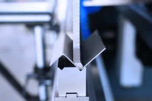
Hydraulic press brake are generally used in the industry for the bending of plates, and the strength is controlled according to the system parameters to achieve different bending effects. The structure includes a support, a workbench and a clamping plate. The workbench is placed on the support.
The hydraulic press brake workbench is composed of a base and a pressing plate. The base is connected to the clamping plate through a hinge. The base is composed of a housing, a coil and a cover plate. The coil is placed In the recess of the seat shell, the top of the recess is covered with a cover plate. This article mainly introduces the working principle of the hydraulic system of the press brake, and what are the precautions when operating it. Let's take a look!
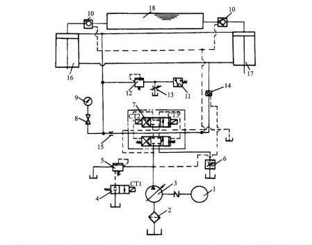
Working principle of hydraulic system of bending machine:
1. Start
All electromagnets must not be energized, and the output oil of the main pump is unloaded through the neutral position of valves 6, 21.
2. The main cylinder goes down quickly
The electromagnets 1Y and 5Y are energized, the valve 6 is in the right position, and the hydraulic control check valve 9 is opened by the control oil through the valve 8. Oil inlet: pump 1-right position of valve 6-valve 13-upper cavity of master cylinder. Oil return circuit: lower cavity of master cylinder-valve 9-right position of valve 6-middle position of valve 21-oil tank.
The slider of the master cylinder descends rapidly under its own weight. Although the pump 1 is at the maximum flow state, it still cannot meet its needs. Therefore, the upper cavity of the master cylinder forms a negative pressure, and the oil from the upper oil tank 15 enters the upper cavity of the master cylinder through the filling valve 14 .
3. The main cylinder approaches the workpiece slowly and pressurizes
When the slider of the master cylinder drops to a certain position and touches the stroke switch 2S, 5Y is de-energized, valve 9 is closed, and the oil in the lower cavity of the master cylinder returns to the tank through the back pressure valve 10, the right position of the valve 6, and the middle position of the valve 21. At this time, the pressure in the upper chamber of the master cylinder rises, the valve 14 is closed, and the master cylinder slowly approaches the workpiece under the action of the pressure oil supplied by the pump 1. After contacting the workpiece, the resistance increases sharply, the pressure further increases, and the output flow of the pump 1 automatically decreases.
4. Keep pressure
When the pressure in the upper chamber of the master cylinder reaches a predetermined value, the pressure relay 7 sends a signal to make 1Y de-energized, the valve 6 returns to the neutral position, and the upper and lower chambers of the master cylinder are closed. The conical surfaces of the check valve 13 and the filling valve 14 ensure a good seal It keeps the main cylinder pressure. The holding time is adjusted by the time relay. During the pressure holding period, the pump is unloaded at the center of the valves 6 and 21.
5. Pressure relief
The return stroke of the master cylinder is over, the time relay sends out a signal, 2Y is energized, and valve 6 is in the left position. Due to the high pressure in the upper chamber of the master cylinder, the hydraulic slide valve 12 is in the upper position, the pressure oil causes the external control sequence valve 11 to open, and the output oil of the pump 1 returns to the oil tank through the valve 11. The pump 1 works at low pressure. This pressure is not enough to open the main spool of the filling valve 14. Instead, the unloading spool of the valve is opened first, so that the oil in the upper cavity of the master cylinder is discharged back to the upper oil tank through this unloading spool opening. The pressure gradually decreases.
When the pressure in the upper chamber of the master cylinder reaches a certain value, valve 12 returns to the lower position, valve 11 is closed, pump 1 pressure rises, valve 14 is fully opened, and the oil inlet path: pump 1-valve 6 left position-valve 9-main Lower cavity of the cylinder. Oil return circuit: upper cavity of master cylinder-valve 14-upper oil tank 15. Realize the rapid return stroke of the master cylinder.
6. The master cylinder stops in situ
When the slider of the master cylinder rises to touch the stroke switch 1S, 2Y loses power, the valve 6 is in the neutral position, the hydraulic control check valve 9 closes the lower cavity of the master cylinder, and the master cylinder stops in its original position. The output oil of pump 1 is unloaded at the neutral position of valves 6 and 21.
7. The lower cylinder is ejected and returned
3Y is energized and valve 21 is in the left position. Oil inlet: pump 1-middle position of valve 6-left position of valve 21-lower cavity of lower cylinder. Oil return path: upper cavity of lower cylinder-left position of valve 21-oil tank. The lower cylinder piston rises and ejects.
3Y is de-energized, 4Y is energized, valve 21 is in the right position, and the lower cylinder piston descends and retracts.
8. Floating blank holder
After the hydraulic press brake piston of the lower cylinder rises to a certain position, the valve 21 is in the neutral position. When the slider of the master cylinder is pressed down, the piston of the lower cylinder is forced to descend along with it. The oil in the lower cavity of the lower cylinder is returned to the oil tank through the throttle 19 and the back pressure valve 20. To maintain the required blank holder pressure in the lower chamber of the lower cylinder, the floating blank holder pressure can be changed by adjusting the valve 20. The upper cavity of the lower cylinder is filled with oil from the oil tank through the center of the valve 21. The relief valve 18 is a safety valve in the lower chamber of the lower cylinder.
Learn more about our products, please visit and subscribe to our Youtube channel
