Pagination:
Part.I
Part.II
Part.III
Part.IV
Table of Contents
3 Bending Processing
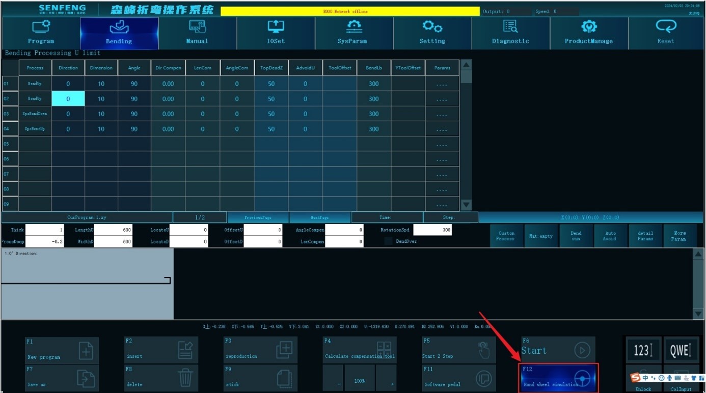
3.6 Description of Bending Process(2)
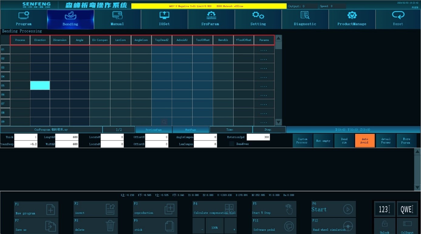
3.6.1 Direction
Function description: the direction in which the work piece needs to be bent, such as: 0°, 90°, 180°, 270°. (The side parallel to the tip of the press knife and close to the knife is the 0° side. The angle required for the other sides to rotate clockwise to the direction of the 0° side is the angle of the current side, as shown in the figure below).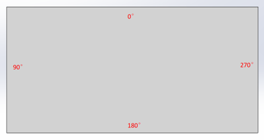
Parameter scope: only valid for the current row.
Parameter setting range: [0,360]
Default value: 0°
3.6.2 Dimension
Function description: the length of the work piece to be bent.(including thickness)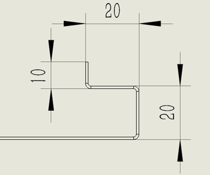
Parameter scope: only valid for the current row.
Parameter setting range: greater than 0.
Default value: 10
3.6.3 Angle
Function description: the opening angle of the work piece to be bent.
Parameter scope: only valid for the current row.
Parameter setting range: [0, 180]
Default value: 90
3.6.4 Direction Compensation
Function description: correct the deviation of the bending direction of the workpiece. For example, the bending direction is 90°, if the actual measured angle of the workpiece is 91°, the direction compensation input is -1°.
Condition: used when the actual direction of the workpiece deviates from the input direction.
Scope: only valid for the current row
Setting range: [-100, 100]
Default: 0
3.6.5 Length Compensation
Function description: correct the bending size deviation of the workpiece. For example, if the bending size is set to 10, if the actual measured bending size is 9.8mm, then the length compensation input is 0.2. For arc bending, it refers to compensating the size of the front straight edge of the arc.
Condition: used when the actual size of the workpiece deviates from the input size.
Range: valid only for the current row
Setting range: [-100, 100]
Default: 0
3.6.6 Angle Compensation
Function description: correct the bending angle deviation of the workpiece. For example, if the bending angle is set to 90°, if the measured workpiece angle is 91°, the angle compensation input is -1. For arcs, it refers to the angle compensated for each arc movement.
Condition: used when the actual angle of the workpiece deviates from the input angle.
Range: valid only for the current row
Setting range: [-100, 100]
Default value: 0
3.6.7 Top Dead Center
Function description: it is the maximum distance of the bottom surface of the upper knife from the upper surface of the workpiece. When the workpiece rotates or returns, the Z axis will rise to the Top Dead Center.
Range: valid only for the current row
Setting range: [0, 1000]
Default value: System Parameters-> Default Parameter [649]
3.6.8 Avoid U
Function description: when the workpiece is pressed flatly or changes the bending edge, the U -axis sends the workpiece forward until the tip of the upper knife gets away from the bending area (When the upper knife is lifted to the Top Dead Center, the workpiece will not be hooked up). This distance is called avoidance distance.
Scope: only valid for the current row
Setting range: [0, 1000]
Default value: 0
3.6.9 Tool Offset
Function description: set the offset of the bending position in the X-axis direction.
The bending position is where the bending knife starts bending. The bending position X is set by the system parameters [600] and [601].
Scope: only valid for the current row
Setting range: 【-10,1.3】
Default: 0 (not used)
3.6.10 Original Length
Function description: the distance between the workpiece center and the edge in this direction
Scope: only valid for the current row
Setting range: [0, 2000]
Default value: when the bending direction is 0°, 90°, 180°, 270°, the system will calculate it automatically and no setting is required. In other directions, the default value is 0 which needs to be set manually.
3.6.11 Circular Arc Radius
Function description: the radius of the arc when bending.
Scope: only valid for the current row and only valid for arc bending.
Setting range: (0, 1000]
Default value: 10
3.6.12 Circular Arc Count
Function description: bending times to form an arc, which is related to Circular Arc Step, Angle, and Circular Arc Radius.
Range: only valid for the current row and only valid for arc bending.
Setting range: [1,1000000]
Default value: 6
3.6.13 Circular Arc Step
Function description: the length of each bend in arc bending, which is related to Circular Arc Count, Angle, and Circular Arc Radius.
Scope: only valid for the current row and only valid for arc bending.
Setting range: [0,1000]
Default value: 3
3.6.14 UO Offset
Function description: because some workpiece sides are too short, which can't be fed forward due to mechanical restrictions, this function needs to be used, that is, the adsorption position of the suction cup on the workpiece is moved backward, so that the workpiece moves forward relative to the suction cup, and the bendable range in this direction becomes larger. It is the offset (vector) of the adsorption/clamping position of the U -axis after UO Offset from the workpiece cener.
Scope: only valid for the current row.
Setting range: [-1000,1000]
Default: 0 (not used)
3.6.15 Death Height
Function description: the set gap distance when pressing the dead edge.
Scope: only valid for the current row and only valid for dead edge bending.
Setting range: [0,10]
Default: 0 (not used)
3.6.16 Avoid Tool
Function description: in the same direction, the previous 2 or more steps are Bend Down, and the current step is Bend Up. Decide whether the direct lifting of the current bending knife interferes with the workpiece. If so, send the workpiece forward. After the lower knife moves to the bending preparation position, the workpiece will be returned to the bending position, and then the bending action will be continued.
Range: only valid for the current row.
Setting range: [0,1000]
Default: 0 (not used)
3.6.17 Avoid Tool Height
Function description: during the operation of Avoid Tool, when the lower folding knife is waiting for the workpiece’s forward movement, its height difference from the surface of the lower press knife (that is, the total height of the bend after the lower bending is avoided).
Scope: only valid for the current row and valid when Avoid Tool is used.
Setting range: [0,2000]
Default: 0 (not used)
3.6.18 Bending Speed
Function description: X and Y axis moving speed during bending.
Scope: only valid for the current row
Setting range: [0,3000]
Default value: 50
3.6.19 Shift Point
Function description: when bending multiple times in the same direction, the Z axis is lifted to the shift point height after each bend, and then the U -axis performs feeding. After the Z axis presses the workpiece, continue to bend. The input value indicates the distance from the surface of the workpiece to the bottom surface of the upper knife.
Scope: valid for the current row, and the pressing down movement of the Z axis.
Setting range: [0, 200]
Default value: 2
3.7 Detailed Bending Parameters
In "detail parameters", set bending parameters such as positioning, dead side, hinge knife, special bending, C acceleration, suction cups, and rods.
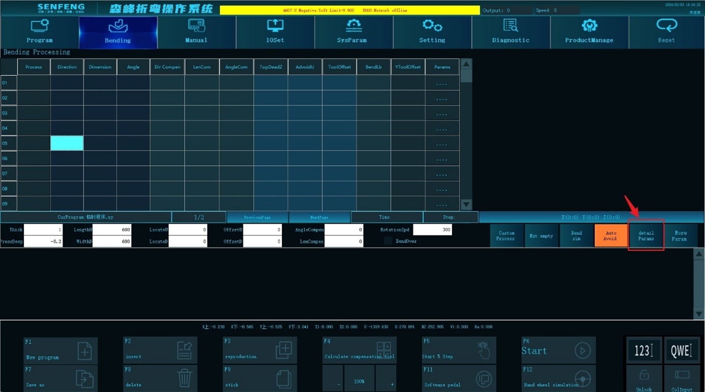
3.7.1 Positioning Way
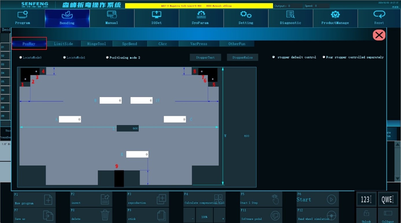
Positioning method 0: If the workpiece is symmetrical, and there is no gap in the U3's ruler position, you can choose this positioning method. Edit Length U, Width D, Offset U, Offset D, and Positioning Width.
Positioning method 1: When the left and right is located, 4 positioning blocks are used. Use the two outer straight corners of the workpiece to locate.
Positioning method 2: When the left and right is located, 2 positioning blocks are used. Use the two inner straight corners of the workpiece to locate.
Positioning test: The positioning block runs to the plate positioning position.
Positioning lift: Lift movement of the positioning cylinder.
3.7.2 Limit Side
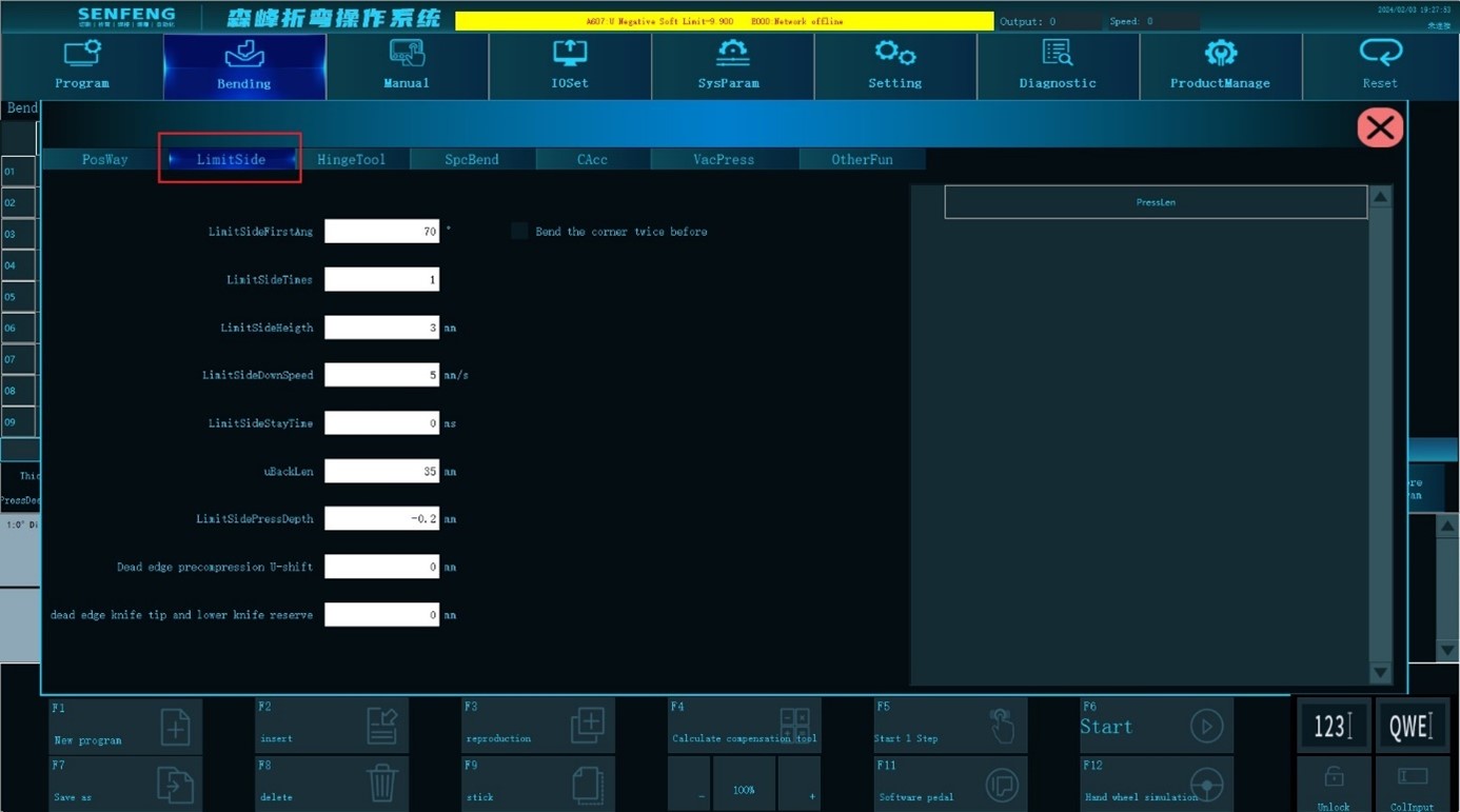
Limt side first angle: Enable the function of the bending 2 times before dead side bending and set the angle of bending for the first time before dead side bending. The unit is ︒.
Limit side times: Count of the same dead side bending action.
Limit side height: When repeating the same dead side bending, the lift height each time(scalar).The unit is mm.
Limit side down speed: During dead side beending, the pressing down speed of the Z axis after the upper knife touches the workpiece, and the unit is mm/s.
Limit side stay time: When the last time the side is pressed, the pressing down time. The unit is s.
U back length: During dead side bending, when the U axis is pulled to the position of the pressed side, the distance (scalar)between the front end of the plate and the knife point. The unit is mm.
Limit side press depth: The pressure depth of the Z axis when pressing the dead side. The depth (vector) calculated from the height of twice the thickness. When the dead height is "0", it takes effect. The unit is mm.
Dead edge precompression U-shift: When the dead side is pre-pressed, the displacement of the U-xis synchronization forward (vector), and the unit is mm.
Dead edge knife tip and lower knife reserve: During bending the dead side, after folding to the minimum angle, the X-axis coordinate position (vector) of the lower knife which supports the plate, and the unit is mm.
Fold the corner twice before dead side bending: Bend twice before pressing the dead side. If you check this option, it will bend twice; if not, it will bend once.
3.7.3 Hinge Tool
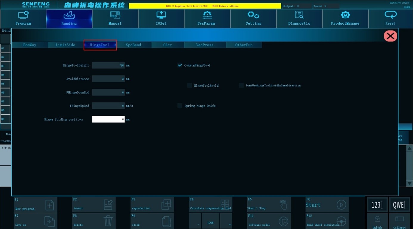
Hinge tool height: After the hinge knife falls, the height difference (scalar) of the lowest point and the bottom surface of the upper knife, and the unit is mm.
Avoid distance: When using a hinge knife, the Z axis is lifted to the shift point, the U axis moves forward, and the Z axis is lifted up to the Top Dead Center to avoid the hinge knife from interference with the board. The unit is mm.
Common hinge tool: Ordinary hinge knife relies on gravity to fall automatically.Check this option before using the ordinary hinge knife. After checking, the program automatically calculates and runs a corresponding avoidance of ordinary hinge knives.
Hinge tool avoid: When processing in the same direction, after each bending, the upper knife lift height will increase the height of the hinge knife.
3.7.4 Special Bending
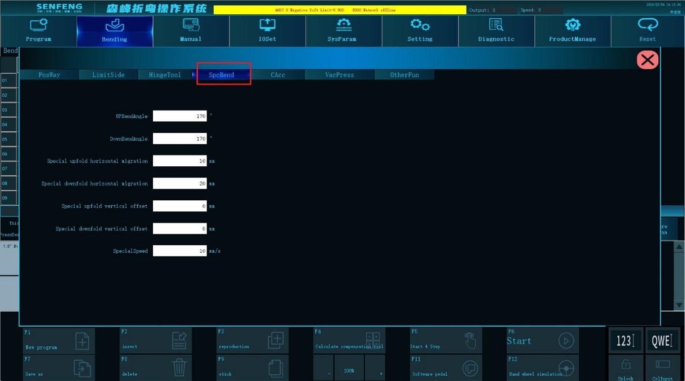
Up bend angle: During the special upper bending process, the pre-folding angle is used when the knife retreats to the specified position before performing normal bending action.
Down bend angle: During the special bending down process, the folding knife retreats to the specified position before performing normal bending action.
Special upfold horizontal migration: During the special upper bending process, the X-axis displacement occurs when the bending knife advances from the pre-bending starting position to the normal bending starting position. Or the X-axis displacement (vector) when the bending knife retreats from the normal bending starting position to the pre-bending starting position. The unit is mm.
Special downfold horizontal migration: During the special bending down process, the X-axis displacement occurs when the bending knife advances from the pre-bending starting position to the normal bending starting position. Or the X-axis displacement (vector) when the bending knife retreats from the normal bending starting position to the pre-bending starting position. The unit is mm.
Special upfold vertical offset: During the special upper bending process, the Y-axis displacement occurs when the bending knife advances from the pre-bending starting position to the normal bending starting position. Or the Y-axis displacement (vector) when the bending knife retreats from the normal bending starting position to the pre-bending starting position. The unit is mm.
Special downfold vertical offset: During the special bending down process, the Y-axis displacement occurs when the bending knife advances from the pre-bending starting position to the normal bending starting position. Or the Y-axis displacement (vector) when the bending knife retreats from the normal bending starting position to the pre-bending starting position. The unit is mm.
Special speed: the moving speed of the X and Y axes during special bending.
3.7.5 Suction Cup and Pressure Rod
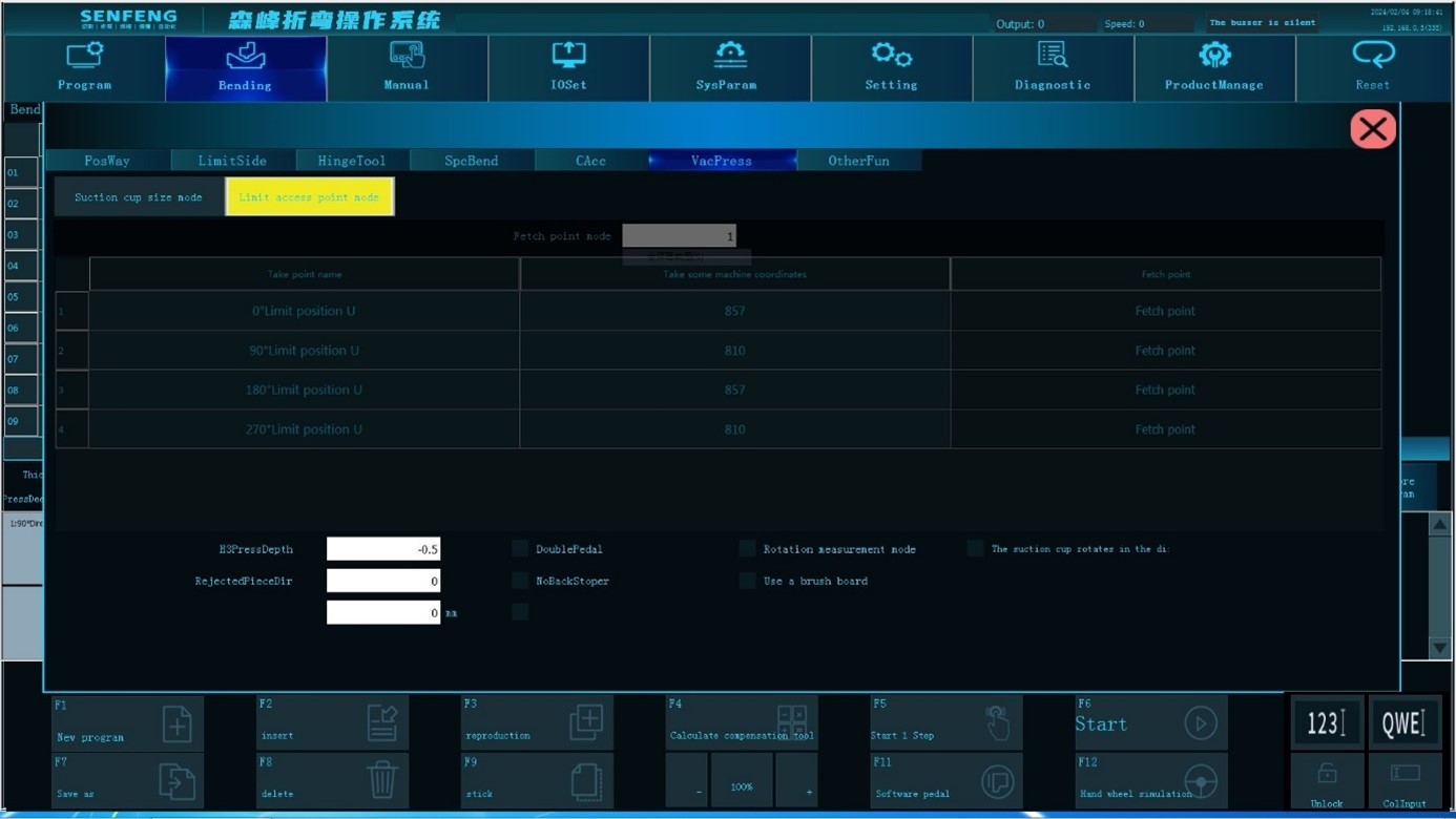
0° limit position U: The limit position of the U-axis when the suction cup/pressing claw is in the 0° direction.
90° limit position U: The limit position of the U-axis when the suction cup/pressing claw is in the 90° direction.
180° limit position U: The limit position of the U-axis when the suction cup/pressing claw is in the 180° direction.
270° limit position U: The limit position of the U-axis when the suction cup/pressing claw is in the 270° direction.
Rejected piece direction: After bending, which side of the workpiece is rotated to the 0° direction for unloading.
Double pedal: The first time to start the signal to perform the positioning action, and the second time to start the signal to run the bending program.
The suction cup rotates in the same direction: The widest side of the suction cup is parallel to the widest side of the plate.
3.7.6 Other Functions
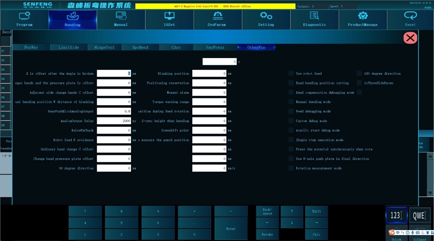
- X is offset after the angle is broken: When the knife retreats after bending, in order to prevent interference with the workpiece, the bending knife first moves along the X-axis direction (vector), and then moves along the Y-axis direction to the bending preparation position. The unit is mm.
- The adjacent side changes hands and the pressure plate is offset: During the adjacent side changing, after the C-axis is rotated to the adjacent side changing angle, adjust the U direction position to the appropriate pressure plate position (vector) of the upper knife. The unit is mm.
- Adjacent side change hands C offset: The angle (vector) of the C-axis rotation when perform the adjacent side changing.
- Manual bending position Z distance of blanking: This function is used when the bending plate is lower than the lower pressure knife and cannot be automatically unloaded. The height at which the Z-axis is lifted when manually picking up the plate from the bending position.
- Robot feed U avoidance: When the robot is loading materials, the distance (scalar) that the U-axis retreats to avoid the robot, in mm.
- Ordinary hand change C offset: The angle (vector) of C-axis rotation during ordinary changing.
- Change hand pressure plate offset: The distance (vector) from the front end of the plate to the tip of the press knife when changing, and the unit is mm.
- Rotation metering times: The number of times of rotational measuring metering that can be executed continuously by starting a program in the rotation measurement mode.
- Blanking position: When the robot unloading equipment releases the workpiece, the default machine tool coordinate position of the U-axis, in mm.
- Positioning reservation: The gap size reserved in the D-axis direction relative to the plate positioning size before positioning, in mm.
- Z synchronization height when bending: The position where the Z axis descends.
- Down shift point: Individually set the shifting point when the Z axis descends. 0 represents the global speed change point.
- Metering position during rotary measurement: In the rotation measurement mode, when the plate is sent to the metering position, the distance between the 0° edge and the tip of the press knife
- Use robot feed: Robot loading and unloading mode.
- Unloading at manual bending position: After bending, the plate stays in the bending position.
- Bending compensation debugging mode: Size and angle compensation can be performed in real time during operation.
- Manual bending mode: Manually place the plate to the bending position.
- Feed debugging mode: Test run without bending the plate.
- Customized debugging mode: Run through teaching point acquisition.
- Acyclic start debugging mode: Only runs once after clicking.
- Single-step execution mode: Each time you press it, one bending step will be executed.
- Press the material synchronously during rotary feeding: Z-axis synchronously drops to the specified height during rotary feeding.
- Use U-axis push plate in final direction: The pressure rod is used to push the material in the last direction of the bending program, aiming at the U-axis travel limit.
- Rotation measurement mode: Used to measure the accuracy of plate rotation and feeding.
- Machine tool aging mode: Each axis of the machine tool reciprocates cyclically between positive and negative limits.
- Three-side adjacent-side changing: Enable adjacent-side changing when only three sides are bent.
3.8 Sub-function Description
3.8.1 Create a New Program
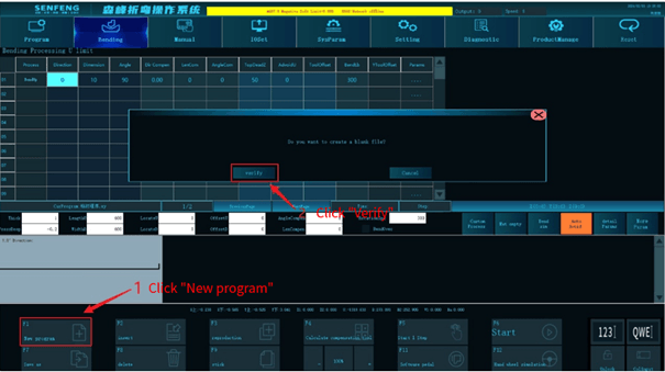
Function description: Clear all the opened bending information with one click and create an empty temporary program file.
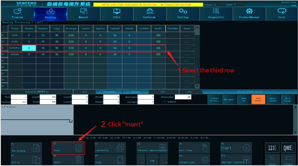
3.8.2 Insert
Function description: Insert a line before any line in the bending program.
Steps:
For example: insert a row before row 3.
- Select row 3.
- Click the "Insert" key.
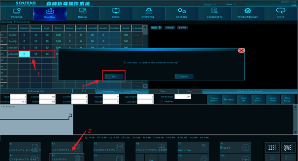
3.8.3 Delete
Function description: Delete selected rows in the bending program.
Steps:
For example: delete row 4
- Select row 4.
- Click "Delete" and the system prompts "Delete the selected step?".
- Click "Yes".
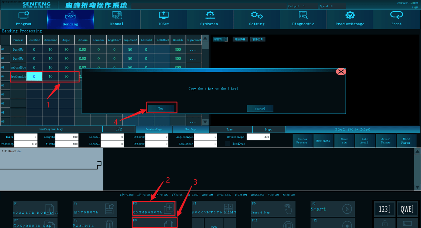
3.8.4 Copy and Paste
Function description: Copy the selected row and paste its bending data to the last blank row.
Steps:
- Select the rows to be copied.
- Click the "Copy" key.
- Click the "Paste" key and it pops up the selection box.
- Click the "Yes" key.
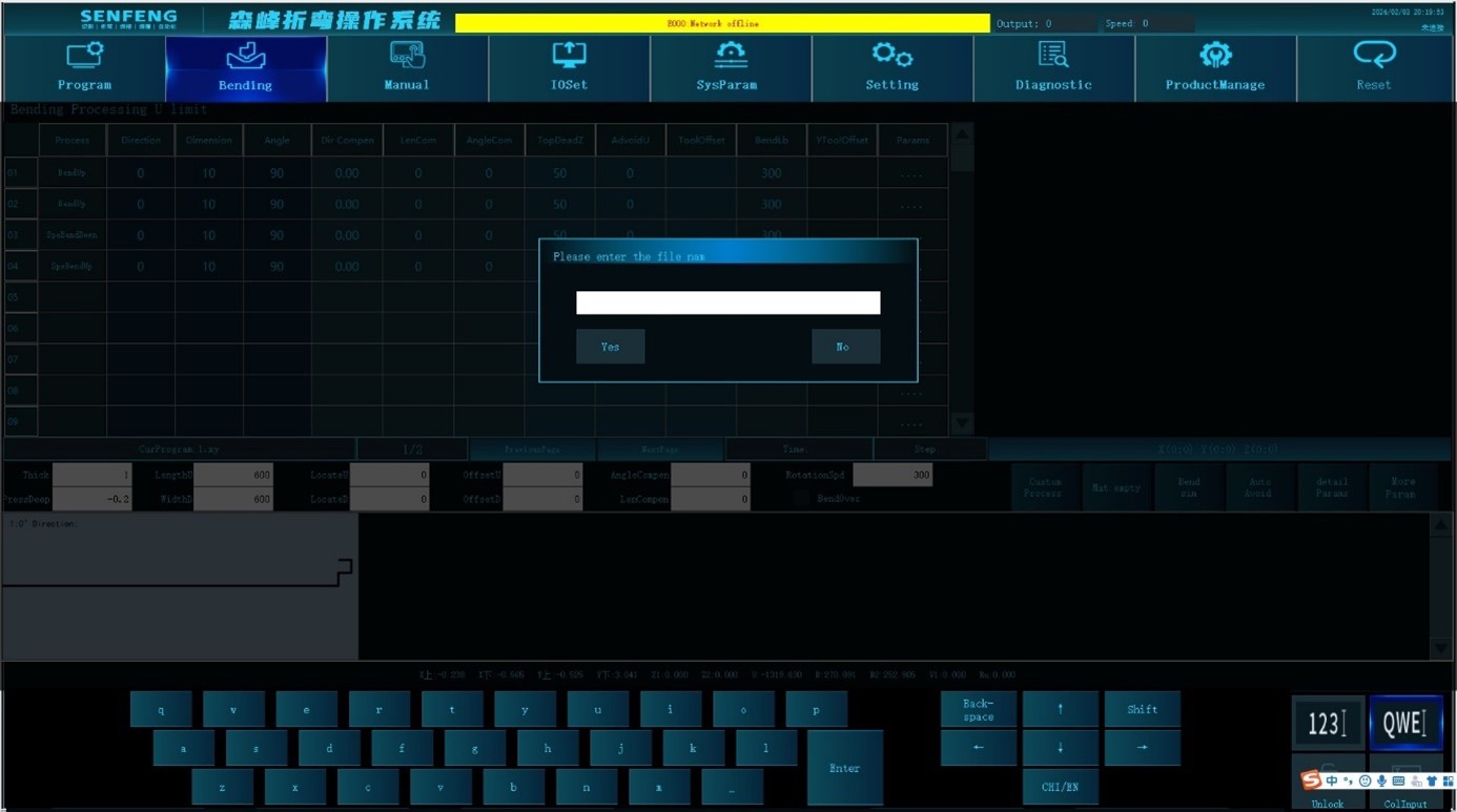
3.8.5 Save as
Function description: Save the program in the NC directory.
Steps:
- Click the "Save As" key and the system pops up the "Please enter the file name" dialog box.
- Use the alphabetical keyboard or numeric keyboard to enter the file name.
- Click "Yes".
3.8.6 Compensation Calculation Tool
Function description: Used when the actual direction of the workpiece deviates from the input direction.
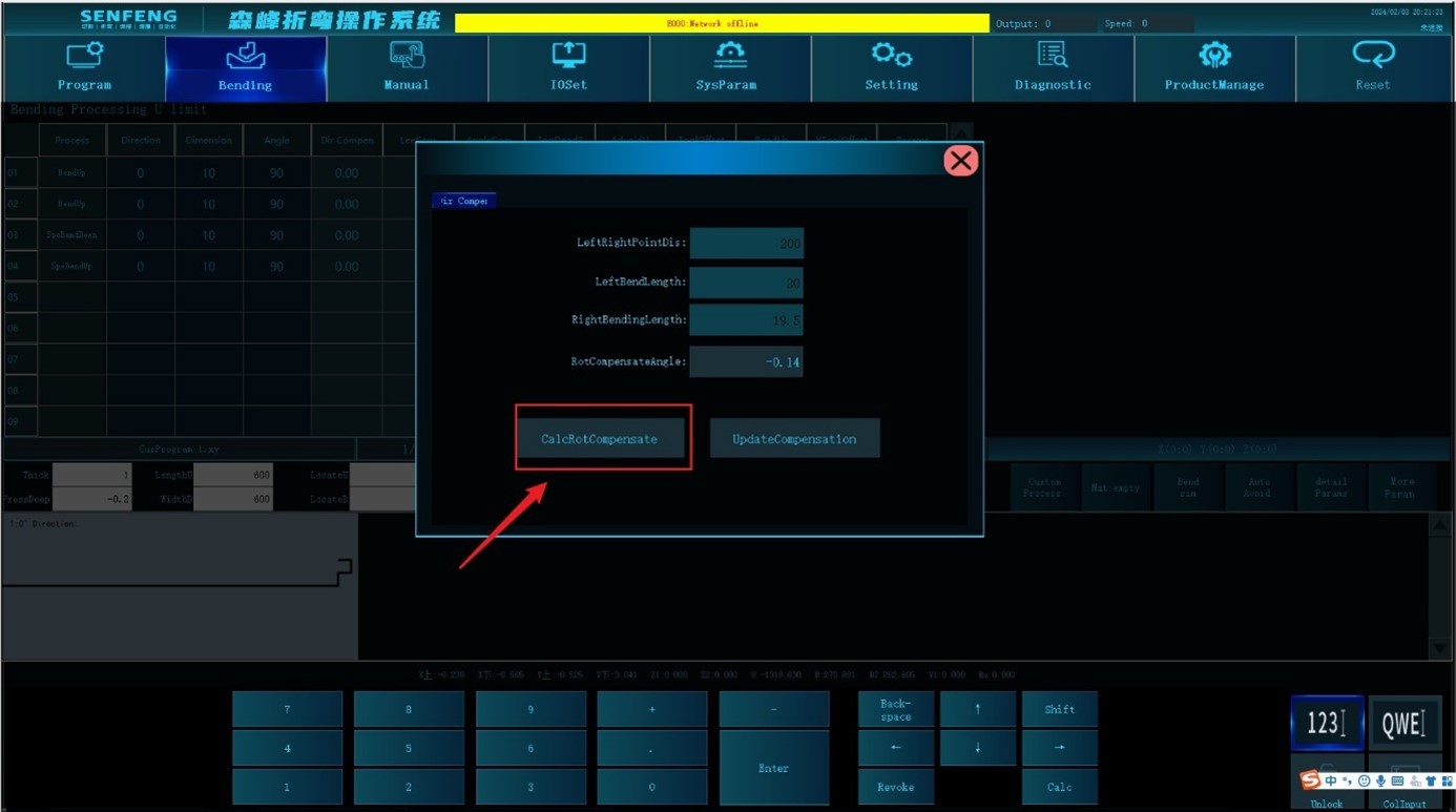
For example: bending direction deviation. The board length is 200, the measured bending length on the left is 20, and the bending length on the right is 19.5. The rotation compensation angle can be automatically calculated by the system.
Steps:
- In the "Bending" interface, click the "Calculate Compensation Tool" button; the system pops up the "Direction Compensation" dialog box.
- Enter the length of the board in " Left Right Point Distance ": 200.
- Enter 20 in "Left Bending Length".
- Enter 19.5 in "Right Bending Length".
- Click "Calculate rotation compensation angle", and the system can calculate the rotation compensation angle to -0.14.
3.8.7 Start from Step N
Function description: You can choose to start from any step.
Steps:
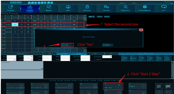
For example: start from step 2.
- Select row 2, and the sub-function "Step Start" key will change to start step 2.
- Click the sub-function "Start 2 step" button, the system will prompt "Start from step 2?".
- After clicking Yes, the bending process starts directly from the second line of the program.
3.8.8 Start(Stop)
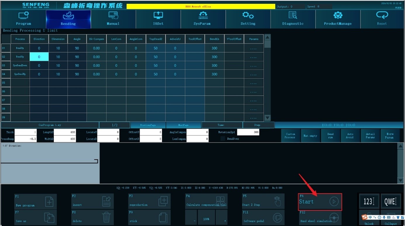
Function description: Start processing from the first step. Click this sub-function key again to pause processing.
3.8.9 Running Speed Adjustment
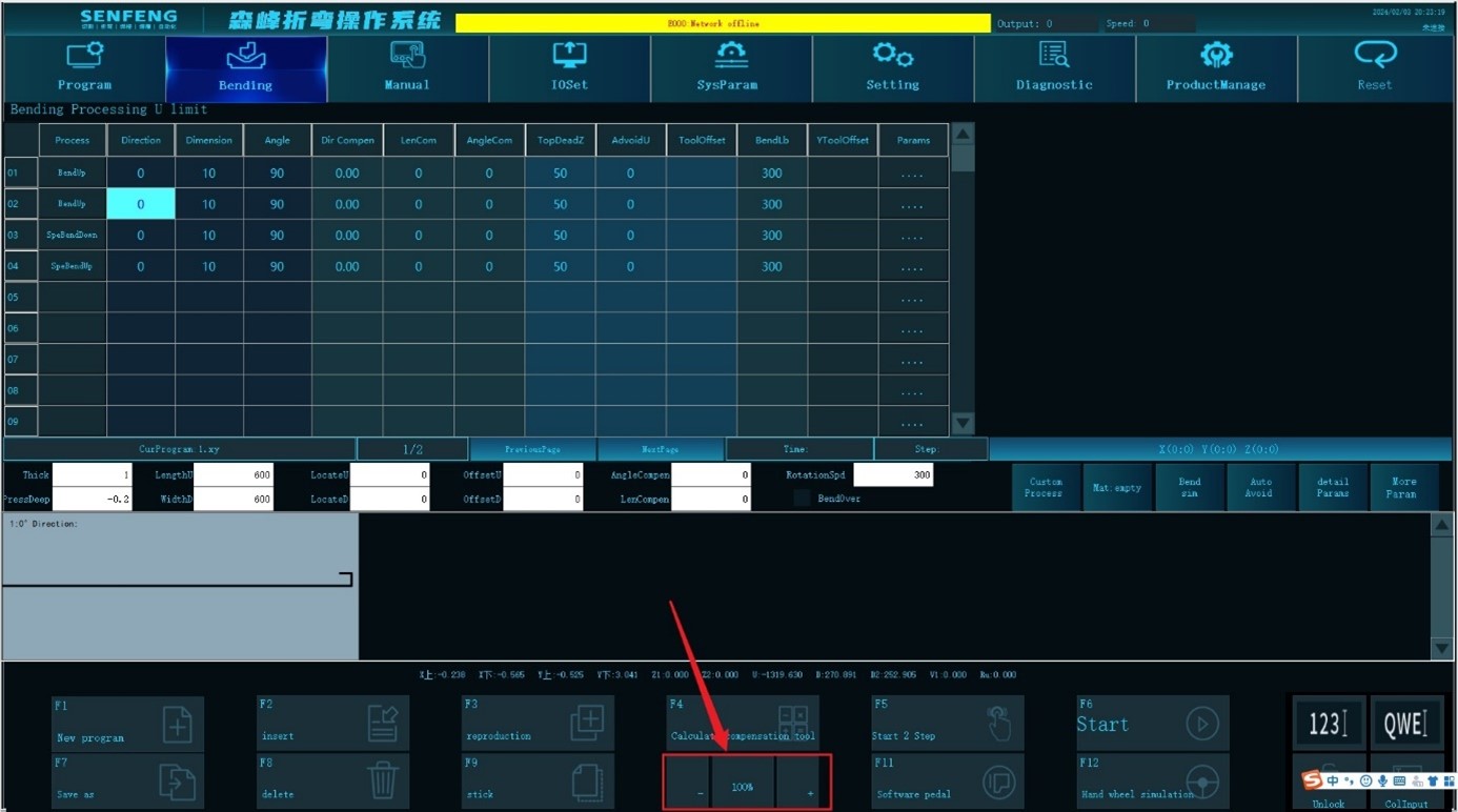
Function description: During processing, the processing speed can be adjusted through the corresponding sub-function keys.
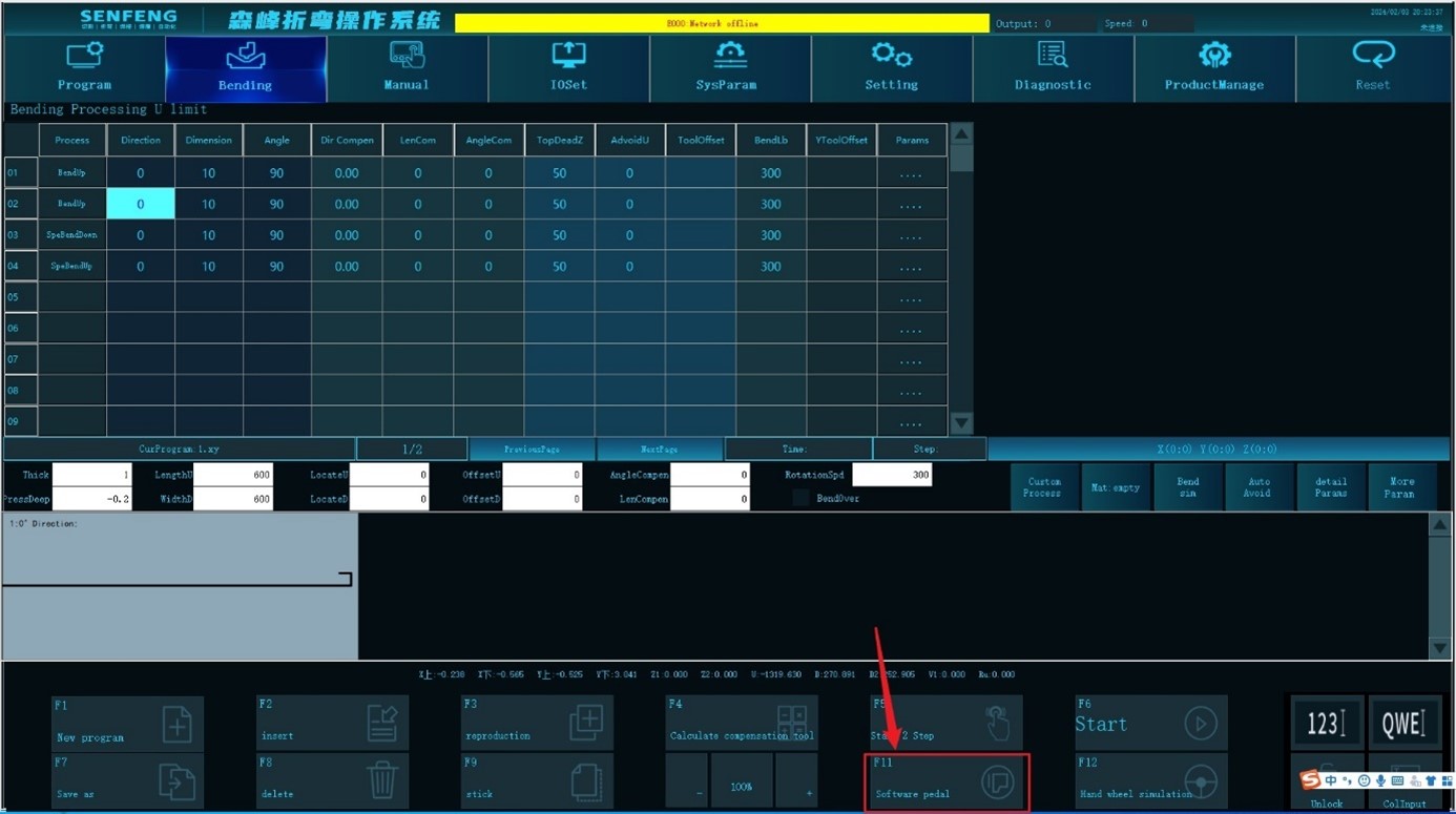
3.8.10 Software Pedal
Function description: After loading is completed, the positioning axis fixes the plate and starts bending.
3.8.11 Handwheel Simulation
Function description: Through the handwheel simulation sub-function, you can use an external electronic handwheel to debug the bending action.
