There are many types of press brake hydraulic system failures. Some of these failures are caused by the failure of a certain hydraulic component. Some are caused by the comprehensive factors of multiple components in the system; some are caused by improper selection of hydraulic oil and hydraulic oil pollution; some are also caused by mechanical, electrical and external factors.
Some of the above failures occurred after slow accumulation, but many occurred suddenly. Many users of hydraulic equipment do not pay attention to the maintenance of the equipment and can only perform repairs after the equipment fails. In order to catch up with the construction cycle or pursue economic benefits, they even make the equipment work with the disease, thus greatly shortening the use time of the equipment.
Usually, troubleshooting of hydraulic equipment takes less than half a day and more than a few days. Users are very worried, and some even have to buy new machines. Hydraulic technology is a new technology, not easy to master.
So, how can maintenance personnel who know little about hydraulic technology analyze and find faults as quickly as possible without special equipment?
Taking the “multifunctional bending machine hydraulic system” as an example, the troubleshooting methods are discussed.
This machine is used for the bending processing of metal products with a diameter of Φ4.5~Φ12mm. It is composed of the main machine, the hydraulic station and the electrical control cabinet. The hydraulic principle is shown in Figure 1.
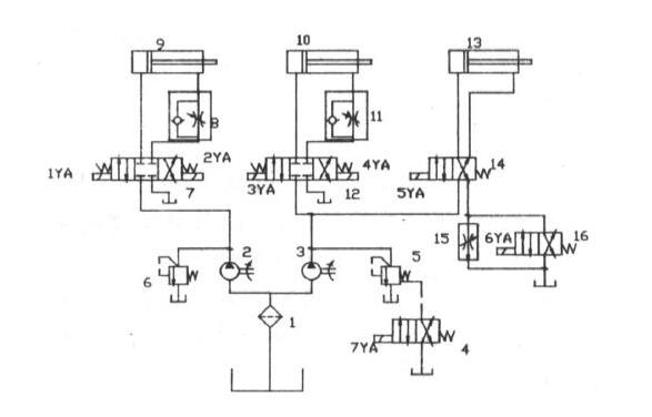
1-filter; 2, 3-dual hydraulic pump; 4, 16-two-position two-way solenoid directional valve; 5, 6-pilot operated relief valve; 7, 12-three-position four-way solenoid directional valve; 8, 11-one-way throttle valve; 9-left bending mechanism hydraulic cylinder; 10-right bending mechanism hydraulic cylinder; 13-compression hydraulic cylinder; 14-two-position four-way solenoid valve; 15-speed control valve
Common faults during the operation of this equipment are: First of all, the noise suddenly increases and the working pressure decreases.
- Observe whether there are bubbles in the compressor lubricating oil in the automobile fuel tank. If there is, it is caused by the system software entering the vapor; if not, go to 2.
By observing whether there are two kinds of vapor bubbles in the compressor lubricating oil, this is the large vapor bubbles on the surface layer, and the compressor lubricating oil is basically not; the other is the compressor lubricating oil with little Vapor bubbles.
The reasons for the first type of steam intake are: the leakage of the plastic hose of the hydraulic oil pump; the destruction of the hydraulic seal of the connection head; the destruction of the seal of the shaft frame of the hydraulic oil pump (the former has a higher probability).
Solution: dismantle and replace the oil inlet plastic hose; dismantle and replace the hydraulic seal of the connection head; dismantle and replace the hydraulic oil pump shaft frame seal.
The reason for the second type of air intake is because the filter 1 is clogged or the degreasing plastic hose is brittle.
Solution: Clean or replace the filter screen 1 or replace the oil-removing plastic hose (the acid and alkali resistant plastic hose must be replaced). If the compressor lubricating oil is very dirty, be sure to replace and replace the new gear oil of the same model and specification. - Adjust the speed control valves 6 and 5, and when adding the load of the system software rated value, touch the hydraulic oil pumps 2 and 3 by hand. If the temperature rises rapidly and the vibration appears abnormal, it indicates that the internal parts of the pump are damaged.
Solution: Replace the pump or repair it.
Secondly, the system software is no noise and no working pressure. First observe whether the remaining oil is returned to the oil return port of the system software is everything normal. If everything is normal, listen to whether there is a sound of compressor lubricating oil fluidity at 5, 62 speed control valves. If so, distinguish which one it is, indicating that the speed control valve is abnormal and can only be cleared; If the remaining oil returned to the oil return hole is abnormal, it indicates that the pump is damaged, repair the pump or replace the pump.
Finally, the system software is no noise, the working pressure is normal when the gear oil temperature is low, and the working pressure is reduced when the temperature is high.
This common fault is very difficult to distinguish and deal with in a basic way. It can be dealt with by segment enumeration: first analyze from the hydraulic schematic diagram, the system software is divided into 3 sub-systems (1 hydraulic cylinder control circuit counts as 1), The sub-system of the electro-hydraulic directional valve 7 is that pump 2 supplies and balances the working pressure oil; the two sub-systems of the electro-hydraulic directional valve 12 and 14 are the two sub-systems of the pump 3 to balance the supply and demand of working pressure oil. The two parts are discussed below.
Prepare standards in advance:
After the operating temperature of the system software is abnormal, the common failure of the working pressure is reduced; the system software selects a hydraulic directional valve with a flat plate connection (if the hydraulic directional valve connected by a bolt can also refer to this method to distinguish);
According to the installation hole and oil inlet and outlet specifications of the electro-hydraulic directional valve 4, 7, 12, 14, etc., four blocking plates are produced and processed, with a thickness of 12mm, and the O-ring seal is installed on the side of the oil inlet and outlet.
First discuss the sub-system operated by the electro-hydraulic directional valve 7.
- Turn off the server and plug the electro-hydraulic reversing valve 7 with the opposite blocking plate to prevent oil leakage. Then, start pump 2 to see if the working pressure rises to the rated current. If it cannot be reached, go to 2; if it exceeds, it indicates that the electro-hydraulic directional valve or hydraulic cylinder is leaking. Check the hydraulic cylinder first. Method: Remove the blocking plate of the modified electro-hydraulic reversing valve 7, replace the electro-hydraulic reversing valve 7, and disassemble the oil inlet of the hydraulic cylinder 9 without rod cavity (assuming that the hydraulic cylinder has been returned), and start the hydraulic oil pump , Make the 2YA power up, and see if there is oil leakage from the disassembled hydraulic cylinder connector. If it leaks, it indicates that the hydraulic seal on the piston rod of the hydraulic cylinder 9 is destroyed and needs to be removed and replaced; if there is no water leakage, it is undoubtedly a common fault caused by the leakage of the electro-hydraulic directional valve 7. Replace it with a new electro-hydraulic of the same model The reversing valve can only be used.
- Replace the speed control valve 6 of the same model. If the working pressure is rated current, it means that the valve is damaged and needs to be replaced. Otherwise, it is a common fault caused by embrittlement of the hydraulic oil pump 2 and needs to be replaced with a pump of the same model.
Check the 2 subsystems of the pump 3 drive.
- Turn off the main engine and plug the electro-hydraulic directional valve 12 with the opposite blocking plate to prevent oil leakage. Start pump 3 to see if the working pressure of the system software is rated current. If it exceeds, refer to the method 1) in hydraulic directional valve 7 for inspection; if it still fails to reach it, go to method 2) in this section.
- Turn off the server, and plug the electro-hydraulic reversing valve 14 with the opposite blocking plate to prevent oil leakage. At this time, the blocking plate at the position of the electro-hydraulic directional valve 12 is still in the system software, start pump 3 to see if the working pressure of the system software is the rated current, if it exceeds, please refer to the hydraulic directional valve 7 in 1) method for inspection; If it still fails, go to method 3) in this section.
- Turn off the server, and plug the electro-hydraulic reversing valve 4 with the opposite blocking plate to prevent oil leakage. Start pump 3 and see if the working pressure of the system software is rated current. If it exceeds, it indicates that the electro-hydraulic directional valve 4 is damaged and needs to be replaced; if it still fails, it must be that the hydraulic oil pump 3 is brittle and needs to be replaced.
note! After searching for common faults, each blocking plate must be removed, and the relative electro-hydraulic reversing valve must be replaced to return to normal.
Basically, this method can be used to analyze the abnormalities of all simple and complicated hydraulic machine systems. It has low requirements for the basic knowledge and technological level of the hydraulic transmission system of the maintenance staff, and has the necessary practical value.
Learn more about our products, please visit and subscribe to our Youtube channel
