Are you looking to achieve precision in metal bending? Correct calibration of the press brake backgauge is essential. This guide walks you through detailed steps to check and adjust the backstop bar’s alignment, both vertically and horizontally, and calibrate the backgauge fingers. By mastering these techniques, you can enhance your machine’s accuracy and avoid costly mistakes. Read on to discover essential tips for calibrating your press brake backgauge.
Why Calibrating the Press Brake Backgauge Matters
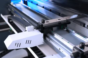
To ensure precise bending, the press brake backgauge must be calibrated to the center of the punch and die. While the backgauge is pre-calibrated during delivery, recalibration is required only if the fingers or backstop bar are misaligned. Additionally, the backgauge must be calibrated with the ETS software before running any program.
I. Checking Backstop Bar Alignment
1. Vertical Plane Calibration
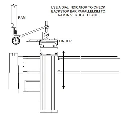
To ensure vertical parallelism between the backstop bar and the ram:
- Attach a magnetic base dial indicator to one of the backgauge fingers.
- Position the X and R axes to reference the ram’s bottom surface.
- Zero the dial indicator on one end of the backstop bar.
- Move the finger to the other end, checking the dial reading.
- The reading should stay at zero. If adjustments are needed, follow the backstop bar calibration procedure.
2. Horizontal Plane Calibration
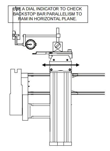
To ensure horizontal parallelism between the backstop bar and the ram:
- Attach the magnetic base dial indicator to a backgauge finger.
- Reference the back surface of the ram.
- Zero the dial at one end of the backstop bar.
- Move the finger to the other end and check the dial reading.
- Calibrate if necessary using the procedure outlined below.
II. Calibrating Gauge Bars
Your press brake includes precision machined gauge bars with a toleranced dimension of 4.000″+.001″. These gauge bars have rubber backing to prevent damage during calibration. Ensure you follow the proper steps for mechanical calibration and familiarize yourself with press brake controls before proceeding.
III. Backgauge Finger Calibration
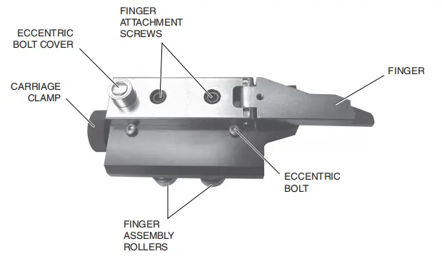
This procedure ensures that both backgauge fingers are equidistant from the backstop bar:
- Set the operating mode to JOG and the control mode to HAND.
- Either execute "Calibrate Back Gauge" from the main menu, or program and move the backgauge to the X=04.000″ calibration position.
- Place two calibration gauge bars across the die opening, spaced several inches apart and near the center of the punch’s length. Ensure the rubber base is on the die, with the chamfered end pointing towards the backgauge.
- Using the palm pushbuttons, jog the press ram down until the punch seats into the “V” notch of each calibration gauge bar. Apply just enough force to slightly compress the rubber backing. Ensure each calibration gauge bar is securely clamped by manually checking for movement.
- Adjust the carriage vertically until the fingers are at the same height as the calibration gauge bars. Mechanical adjustment to the backgauge is performed behind the press brake. For safety, depress and maintain the backgauge STOP pushbutton in its locked position before working in the backgauge area.
For machines equipped with a Manual-R system, use the backgauge carriage handwheel. For machines with a Power-R system, program the correct position.
- Move one backgauge finger to the end of one calibration gauge bar. On a Manual-Z system, loosen the carriage clamp and slide the finger into position. On a Power-Z system, program the correct position.
Adjust the finger to the calibration position:
- Use a 5/16″ hex key to loosen the two socket head cap screws that attach the finger to the finger block.
- Remove the steel cap from the boss that encloses the eccentric bolt at the rear of the finger.
- Using a 7/16″ hex key, turn the eccentric bolt to adjust the finger firmly against the calibration block. Use gentle hand pressure to keep the finger parallel to the edge of the finger block.
- Remove the calibration gauge bars and re-enable the backgauge by rotating the backgauge stop button 1/4 turn clockwise.
- Move the second backgauge finger to the end of the second calibration gauge bar and repeat the adjustment steps from step 6.
- Adjust both fingers so that the contact pressure between the fingers and the gauge bars is identical.
- Once adjustment is complete, replace the eccentric bolt cap and retighten the two screws.
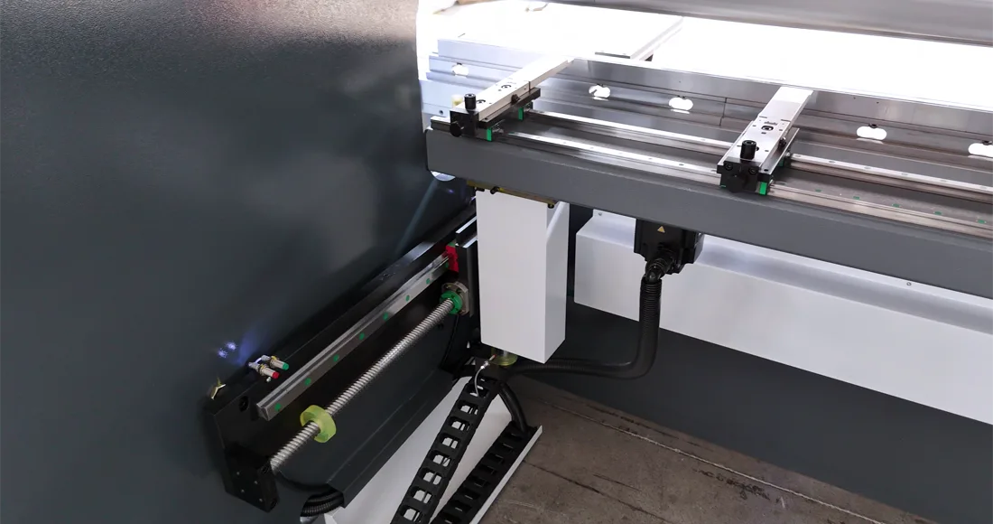
IV. Backstop Bar Calibration
1. Vertical Plane Adjustment
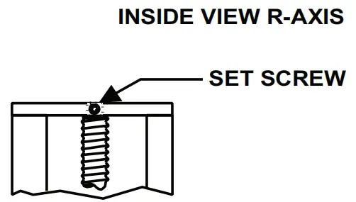
To adjust the backstop bar’s vertical position:
- Loosen the set screw on the R-axis top plate.
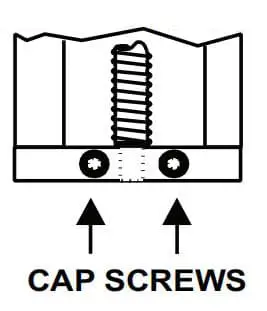
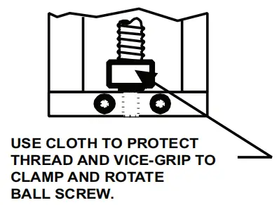
- Use vice-grip pliers on the ball screw (protected by a cloth) to adjust height.
- Once adjusted, tighten the set screws and remove the pliers.
2. Horizontal Plane Adjustment
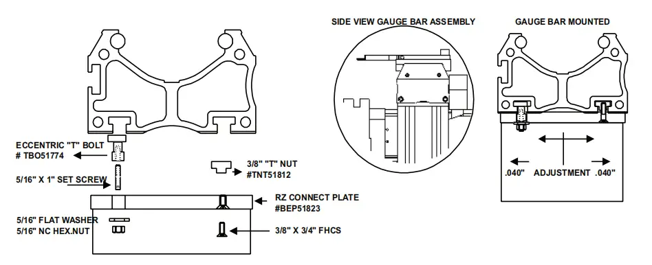
To adjust the backstop bar’s horizontal position:
- Loosen the T-nuts and rotate the T-bolts until the backstop bar is parallel with the ram.
- Tighten the T-nuts once parallelism is achieved.
Conclusion
Calibrating the Press Brake Backgauge is essential for maintaining accuracy in metal bending operations. By following the steps outlined in this guide, you can ensure that your machine operates efficiently and precisely. Regular calibration minimizes errors, reduces downtime, and prolongs the lifespan of your equipment. Whether you're adjusting the backstop bar or calibrating the backgauge fingers, these procedures are key to achieving consistent results.
For more information on press brake maintenance and optimization, explore other resources on our site and keep your workshop running smoothly!

