To achieve greater precision in bending elevator sheet metal components, the Sheet Metal Bending Process Parameters, including the bending radius (R-angle) of widely used materials such as SPC, SPHC, SUS304, and 804-GG, were meticulously measured at a 90° angle using a CNC press brake in the sheet metal workshop. An optical measuring instrument was employed to determine the exact bending radius, while vernier calipers were used to accurately calculate the bending coefficient.1
The test results offer valuable reference data, supporting the selection of optimal bending tooling. This helps to enhance R-angle accuracy during the bending process and significantly improves the precision of dimensional calculations.
Significance of Testing in Sheet Metal Bending
The bending radius (inside R) and bending coefficient are critical parameters that directly influence the quality of the sheet metal bending process. The bending radius is affected by factors such as the bending tool, material thickness, and material performance, while the bending coefficient is determined by the material thickness, bending radius, and bending angle. Additionally, the bending coefficient plays a key role in calculating the unfolded dimensions of the workpiece.
The current formula for calculating the 90° bending factor is expressed as α = 1.36t + 0.43R (where t is the material thickness). However, common errors can arise when calculating the bending factor, such as:
- The difference between the nominal t value and the actual material thickness.
- Deviation between the actual inside bending radius (R) and the required R shown in the drawing, often assumed in calculations.
- Inaccuracies from using an R gauge, where values below R3 are approximated as 0.25 and above R3 as 0.5.
- Failure to account for material and bending method differences when determining the bending R.
These errors can accumulate, especially when a workpiece undergoes multiple bends, resulting in poor dimensional accuracy in the final product.
To overcome these challenges, this experiment measured the actual thickness of various bending materials, employed an optical measuring instrument for precise inside and outside radius measurements, and calculated the real bending coefficient. Comparing these results with the formula aids in selecting the correct bending dies, improves R-angle accuracy, and enhances the precision of dimensional calculations.
Test Scheme for Sheet Metal Bending Process Parameters
Test Materials
The materials tested in this experiment were SPCC, SPHC, SUS304, and 804-GG, all sourced from our company. Each material had varying thickness specifications, detailed in Table 1, to evaluate their behavior during the bending process.
Table 1 Test materials and thickness (mm)
| Thickness t/mm | 1.0 | 1.2 | 1.5 | 2.0 | 2.3 | 2.5 | 3.0 | 3.2 | 4.5 | 6.0 |
| SPCC | √ | √ | √ | √ | √ | √ | ||||
| SPHC | √ | √ | √ | |||||||
| SUS304 | √ | √ | √ | √ | √ | |||||
| 804-GG | √ |
Test Specimen
Each sample used for the experiment measured 100mm x 100mm, with production carried out using laser cutting and blanking. This ensured that the dimensional accuracy of the samples was maintained within a 0.1mm tolerance, providing reliable data for analysis.
Test Equipment
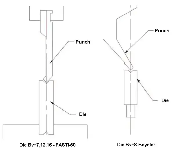
The bending equipment used included a CNC press brake located in the sheet metal workshop. The V-groove dies used for the experiment were from FASTI-50 and Beyeler, and the scimitar upper die was chosen for precise bending, as shown in Figure 1.
For additional testing, a three-point bending machine (3P250) was employed. The straight knife upper dies selected for this experiment were the pointed cutter R7 and the round cutter R9, as illustrated in Figure 2, to compare performance across different die types.
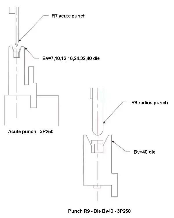
Table 2 The parameters of press brake, punch & die
| Die opening (Bv/mm) Press brake & punch type | 7 | 8 | 10 | 12 | 16 | 24 | 32 | 40 | |
|---|---|---|---|---|---|---|---|---|---|
| V opening (Gooseneck punch) | Beyeler | √ | |||||||
| FASTI-50 | √ | √ | √ | ||||||
| Three-point (straight punch) | 3P250 | √ | √ | √ | √ | √ | √ | √ | |
Test Method for Measuring Bending Parameters
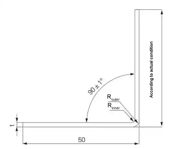
To ensure accurate results, the true thickness of each test specimen was measured using a micrometer, with four pieces averaged for each material thickness. The specimens were then bent using various bending dies, set at a bending angle of (90 ± 1)°, with a target length of 50mm on one side, as shown in Figure 3.
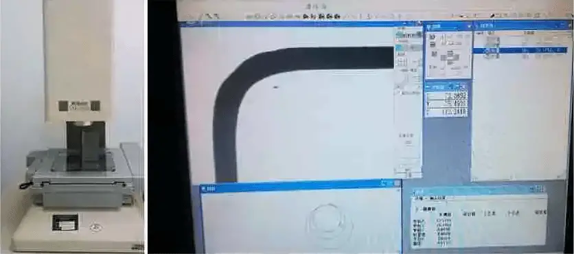
Each thickness specification was tested five times to ensure consistency. Once the bending process was completed, the bending angle contours were scanned with an optical measuring instrument to accurately determine both the outer bending radius (R outside) and the inner bending radius (R inside), as depicted in Figure 4.
A vernier caliper was then used to measure the lengths of both sides, allowing for the calculation of the bending coefficient. This process was repeated five times for each material thickness, with the average value used for further analysis.
Test Results and Analysis
The table of test results provides data including the actual material thickness, inner and outer radii for 90° bends, bending coefficients, and thinning rates for each material.
Actual Material Thickness Table 3 compares the nominal and actual thicknesses of the test specimens, as measured by a micrometer. It shows that the actual thickness of SPCC is within 0.03mm of its nominal thickness, while the uncoated SUS304 was approximately 0.07mm thinner. For the 4.5mm hot-rolled SPHC plate, the measured thickness was 4.2mm.
Table 3 The actual thickness of the test materials (mm)
| Nominal thickness | 1.0 | 1.2 | 1.5 | 2.0 | 2.3 | 2.5 | 3.0 | 3.2 | 4.5 | 6.0 | |
|---|---|---|---|---|---|---|---|---|---|---|---|
| Real thickness | SPCC | 1.00 | 1.18 | 1.48 | 2.01 | 2.50 | 2.97 | ||||
| SPHC | 3.13 | 4.20 | 5.91 | ||||||||
| SUS304 (Remove film) | 0.93 | ||||||||||
| 804-GG | 2.26 | ||||||||||
Bending Inside Angle (Rinner) The inside bending radius (Rinner) is influenced by the material, plate thickness, bending method, and tooling. Among these factors, material type showed the most significant influence:
- Rinner(SUS304) > Rinner(SPCC): For instance, with a V-groove width (Bv) of 12mm, the Rinner for 1.2mm SPCC is 1.85mm, while SUS304 measured 2.09mm.
- The impact of plate thickness on Rinner is minor when using the same bending die. For example, when Bv = 12mm in three-point bending, SUS304 plates with thicknesses ranging from 1.0mm to 2.0mm had Rinner values between 2.33mm and 2.51mm.
- Rinner(three-point) > Rinner(V-groove): A comparison of identical V-groove lower dies (Bv = 7mm, 12mm, 16mm) showed that Rinner in three-point bending was larger than in V-groove bending.
- Larger Bv leads to larger Rinner: With three-point bending, wider slot widths (Bv = 24mm, 32mm, 40mm) resulted in Rinner values of approximately 4.0mm, 4.7mm, and 5.9mm, respectively. Therefore, material, bending method, and slot width all affect Rinner, warranting careful consideration during setup.
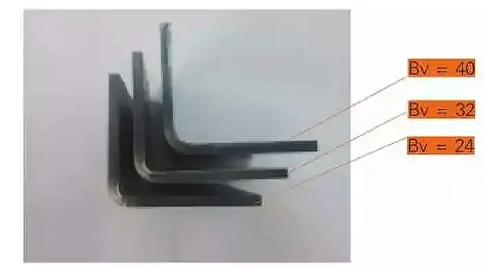
Thickness Reduction and Outside Bending Radius (Router) The difference between Router and Rinner was used to calculate the average thickness near the bend (t’ = Router - Rinner). The reduction ratio (η) was determined as η = (t – t’)/t.
The data indicates that thickness reduction occurred in all test cases, with most reduction ratios falling between 6% and 15%. The relationship between material thickness, bending method, and slot width on thinning is complex, though SPHC exhibited a lower reduction rate, around 4% to 6%.
Bending Roundness The optical measuring instrument calculated roundness values for Rinner and Router:
- When Bv = 7-16mm, the roundness values were minimal, typically ≤ 0.05mm, indicating high precision.
- At Bv = 24mm, 32mm, and 40mm (all in three-point bending), the roundness values exceeded 0.1mm, suggesting that larger groove widths decrease the roundness of the bend.
Bending Coefficient (α) The table also compares measured and calculated values for the bending coefficient (using the formula α = 1.36t + 0.43Rinner). The differences were small, confirming that the formula is applicable for a wide range of conditions. The bending coefficient depends primarily on the material thickness (t) and actual Rinner, with material type, plate thickness, and tooling affecting Rinner.
For new materials or varying thicknesses, it is essential to measure both the actual thickness and Rinner to ensure precise results.
Conclusion
From the analysis, several key conclusions can be drawn:
- Test Findings: The results reveal the bending Rinner, Router, and bending coefficients for commonly used sheet thicknesses of SPCC, SPHC, SUS304, and 804-GG when processed using CNC press brake machines such as Beyeler, FASTI-50, and 3P250.
- Influence of Material: Rinner is influenced not only by the bending die but also significantly by the material type. The tests indicate that Rinner for SUS304 is slightly larger than that for SPCC under identical bending conditions.
- Bending Method Considerations: When other bending parameters remain constant, Rinner is generally greater in three-point bending compared to V-groove bending. This suggests that the choice of bending method should be factored into the selection of the bending coefficient.
- Universal Bending Coefficient Formula: The bending coefficient calculation formula, α = 1.36t + 0.43Rinner, is found to be universally applicable. By accumulating the actual thickness data of commonly used bending materials along with their corresponding Rinner values from bending molds, a more accurate bending coefficient can be determined.


We thank for the help in choosing the press brake