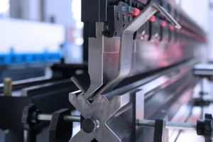
Ever wondered how today’s manufacturing achieves such high precision and efficiency? The answer lies in the hydraulic ironworker—a highly versatile machine designed to cut, punch, shear, and bend metal with remarkable ease. In this article, we’ll dive into the core functions, benefits, and reasons why the hydraulic ironworker has become indispensable in industries like bridge construction and military manufacturing. Prepare to discover the powerful capabilities of this essential tool!
What Is Hydraulic Ironworker
A hydraulic ironworker is a powerful, multi-functional machine designed to streamline and enhance metal fabrication processes. Combining a variety of essential operations—such as cutting, punching, shearing, and bending—into a single piece of equipment, it provides unparalleled versatility in handling a wide range of materials. Also referred to as a hydraulic steelworker, this machine leverages hydraulic power for superior precision, reliability, and efficiency in performing these tasks.
Key Features and Advantages of Hydraulic Ironworkers:
- Versatility: Hydraulic ironworkers can handle various materials, including mild steel, stainless steel, and aluminum alloys. This makes them suitable for a broad spectrum of applications in metalworking, ranging from light-duty to heavy-duty tasks.
- Multi-Station Configuration: These machines typically come with separate workstations dedicated to specific functions such as punching, shearing, and bending. This layout allows for greater flexibility and productivity since different operations can be performed simultaneously or quickly switched between, without the need for additional setups.
- Hydraulic Power for Precision: Utilizing hydraulic systems, these ironworkers deliver a smooth, controlled application of force, ensuring cleaner cuts, more accurate holes, and uniform bends. This precision minimizes material wastage and reduces the likelihood of errors compared to mechanical systems.
- User-Friendly Interface: Designed with intuitive controls, hydraulic ironworkers are accessible to operators with a variety of skill levels. The machines are equipped with safety features that help prevent accidents and ensure safer operation.
- Energy Efficiency: Compared to using multiple individual machines for each task, a hydraulic ironworker is much more energy-efficient, as it consolidates multiple functions into one machine. This reduces energy consumption and helps lower operational costs.
- Low Maintenance Costs: With its integrated design, a hydraulic ironworker requires less frequent maintenance compared to maintaining several separate machines. This not only reduces downtime but also cuts costs associated with repairs and parts replacements.
Key Industries Benefiting from Hydraulic Ironworkers:
- Metallurgy: Used for processing raw metal into shapes that meet specific industrial needs.
- Structural Steel Fabrication: Vital in manufacturing large-scale steel components for bridges, buildings, and other infrastructure projects.
- Telecommunications and Power Distribution: Helps in producing metal parts for electrical and communication equipment, including poles, towers, and frames.
- Military and Defense: Plays a critical role in fabricating high-strength components required for military and defense applications.
- Automotive and Aerospace: Widely used to produce various metal parts for vehicle and aircraft manufacturing.
While both hydraulic and mechanical ironworkers exist, hydraulic models have become the preferred choice due to their superior control, greater versatility, and enhanced efficiency in metal processing. Whether you're dealing with high-volume production or intricate, precision-based tasks, hydraulic ironworkers provide a reliable, cost-effective solution for modern metalworking needs.
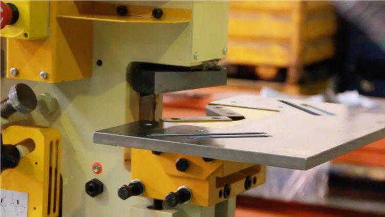
Performance & Features
The hydraulic ironworker machine offers exceptional versatility within its rated specifications, efficiently performing flat bar cutting, hole punching, and notching operations. This multifunctionality streamlines metal fabrication processes, reducing the need for multiple specialized machines.
With the addition of optional equipment, the machine’s capabilities expand significantly. It can execute specialized cutting, punching, and bending operations to produce complex shapes and profiles. This adaptability allows fabricators to tackle a wide range of custom projects without investing in separate machinery.
The steelworker machine incorporates a robust hydraulic driving system, ensuring consistent power delivery and smooth operation across various metalworking tasks. This hydraulic system is complemented by an advanced performance monitoring and overload protection device. This crucial safety feature safeguards both the operator and the machine by automatically adjusting or halting operations when load limits are approached, preventing potential damage and ensuring longevity of the equipment.
The integration of these features results in a highly efficient, versatile, and safe metal fabrication solution suitable for diverse industrial applications. The machine’s design prioritizes productivity without compromising on precision or operator safety, making it an invaluable asset in modern metalworking facilities.
Structure of Hydraulic Ironworker
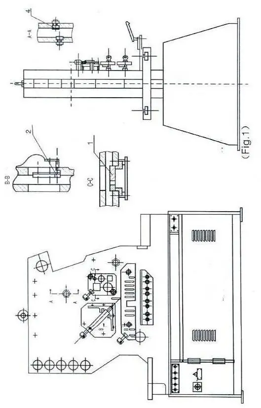
The bed of the ironworker machine is composed of body, seat, bracket for the section, bracket for angle and cutting table.
The body and the seat are of welded construction, others are of bolt-connected ones which give the machine great strength and rigidity and allow easy dismounting during repairing the ironworker machine.
An adjustable pad for limiting the left-right movement of the blade is mounted on the left-right housing.
An adjustable hold-down for holding the angle to be cut is fitted on the angle cutting station.
With the square and round aperture of various sizes on the section cutting blade, the ironworker machine is able to cut various square and round bars.
The shearing table is fitted with a robust hold-down which is adjustable to any thickness of material and with a stop finger to allow accurate cutting of angle and flat bar at any angle.
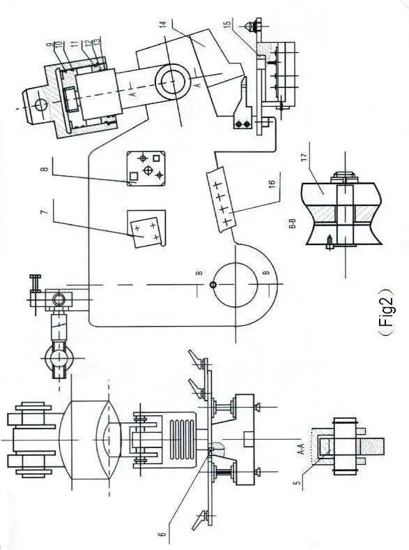
This station comes equipped with sturdy blades designed to handle a variety of cutting tasks. It features four distinct apertures for cutting angle iron, round bars, square bars, flat bars, and notching steel plates.
With additional tooling, the same cutting apertures can be adapted to also process channel and joist bars.
The beam is connected to the hydraulic oil cylinder, with its top end hinged to the frame. Powered by the oil cylinder, the beam swings to perform precise cuts.
The upper notching blade is securely mounted on the beam, while three lower blades are positioned on the die seat. These lower blades can be adjusted on both sides to provide the necessary cutting clearance.
For accurate notching, the station is equipped with both a side gauge and a back gauge on the notching table, ensuring the plate is positioned correctly during the cutting process.
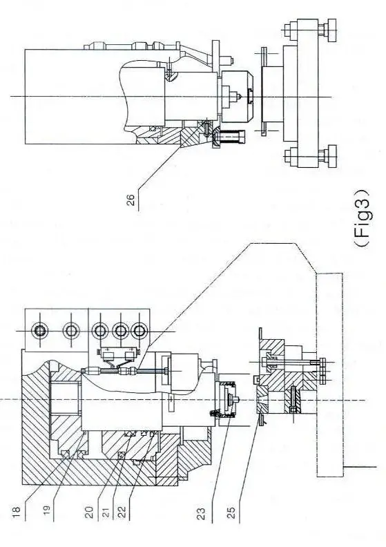
The punch is fixed on the lower end of the piston rod of the oil cylinder with locking nut and the die is fixed in the adapter.
After the punch and die are aligned with each other, the bolts should be tightened.
To punch square and long round hole, there is a guide on the side surface of the piston rod, besides, along round positioning slot is milled on the pad and the top of the punch to prevent the punch from being turned.
With additional toolings on this station, bending, tube notching, louver punching, large hole punching, channel, joist, web punching work can all be performed.
Hydraulic System
1) After the motor is started, oil flow, which is compressed out from the pump (1), returns to the oil tank via the solenoid valve (4) to enable the pump to be discharged.
2) By turning the mode knob to the “SINGLE” position and depressing the foot pedal for punching hole, the electromagnet YV5b is turned on, hydraulic oil flows into the top chamber of the punching unit through the valve(3), the oil in the low chamber returns to the oil tank via the valve(3), so the punch moves downward to perform punching.
When the punch touches the limit switch at the lower dead point, YV5b is turned off, the pump is set to be discharged, so the punch is stopped. when the foot pedal is released and YV5a is turned on, the hydraulic oil flows to the lower chamber of the hydraulic cylinder, the punch moves upwards to touch the limit switch at the top dead point, so the YV5a is turned off and the punch is stopped at the top dead point.
In the same way, by depressing the foot pedal for cutting section, YV7b is turned on, oil enters the top chamber of the oil cylinder for cutting section, oil in the lower chamber returns to the oil tank via the solenoid valve(3), so the blade moves downward to perform cutting work.
When the blade touches the limit switch at the low dead point, YV7b is turn off, the blade is stopped at the dead point.
When the foot pedal is released, YV7a is turned on, oil enters the lower chamber in the oil cylinder for cutting cylinder, oil in the top chamber returns to the oil tank, so the blade moves upward, as the blade touches the limit switch at the top dead point, it is there.
3) By turning the mode knob to the “INCHING” position and depressing the foot pedal for punching hole, the electromagnet YV5b is turned on, a part of hydraulic oil enters the top chamber in the oil cylinder for punching hole,
4) Max working pressure in the hydraulic system is 250kgf/cm 2(24. 5MPa). The adjustment range of pressure in the overflow valve is 25MPa. The entire hydraulic system is protected against overload by the overflow valve.
5) The steelworker machine is fitted with a pressure gauge which is used to check the pressure in the hydraulic system and adjust pressure after replacing hydraulic elements.
To use it, the end screw on the valve block is removed, mount the pressure gauge and tighten it, then turn on the cock of the pressure gauge.
The pressure valve is shown on the gauge during operation.
The pressure in the hydraulic system before delivering the machine has been properly adjusted to the delivering the ironworker machine has been properly adjusted to the max working value, so please do not re-adjust at your option.
Steps to Operate tehe Ironworker Machine
The metal worker is a great machine to use for metal fabrication and for making bends on schedule 40 piping or standard 11 to 16 gauge tubing with the hydraulic bender. The metal worker has 3 main components; the punch, shear (angle & flat), and notcher. It is hydraulically operated machine and can cut through thick sizes of metal. Ask Techshop staff for specifics for each component.
To start on the Metal worker, make sure it is plugged in and then push the green start button to start the hydraulics. You are now ready to go. To actuate the machine make sure that your hands are completely free and then use the foot pedal to actuate it.
Step 1: Using the Punch
The punch can be used with metal up to 5/8" thick and there is a whole set of round and square size die's that can be changed out. Ask the Techshop staff to install the one correct for your project. Once the correct die is installed, utilize the wrench for the machine and lower the safety guard down onto your material. The guard should be lowered tight enough that your material cannot be lifted at all, but it should still be able to slide somewhat freely. You can use a center punch to mark where you need the hole and then slowly lower the die on the metal worker to line up with your mark and then continue to punch all the way through.
Step 2: Using the Shear
The shear can cut up to 1/2" steel flat stock and up to 1/4" angle iron. There is a adjustable guide for the flat stock that should again be tight enough to prevent the metal from lifting up, but you should be able to still slide your stock freely. For the angle sock there is a lock screw that should be tightened down tight against your material. After you have your guide/stops set depress the pedal to actuate the machine.
In order to cut your material at the right distance on the flat shear section make sure everything is clear from the shear and then depress the pedal and hold it until the shear is fully actuated. Continue holding it and use a tape measure to measure the distance from the the outside of the guide to the shear face. Offset your measurement this distance to cut the correct desired length. For the angle stock section you can see your line through the top of the guide.
Step 3: Using the Notcher
The notcher is just like the other components of the metal worker, however the guide is not adjustable. Simply hold your material securely under the notcher and then depress the pedal to actuate the machine.
Step 4: Using the Bender
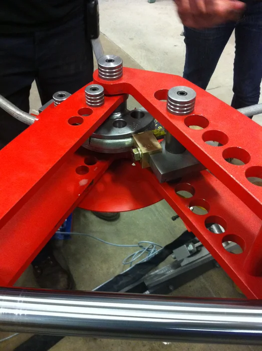
The hydraulic bender attachment for the iron worker enables you to create specific bends in schedule 40 pipe, tubing, and square stock. Setup the machine with the appropriate die's for your material and size and slide your stock into place. Secure it using the material loop and material lock (set screw). On each of the drive die's (rounded die) there are 3 drive holes. To begin you should be on drive hole 1. Before you begin make sure you lubricate your material and the die's with either WD-40 or grease. Once you are set, turn the metal worker on and switch the control box to "accessory". Now you are ready to control the bender with the "in/out" control box. Bend your stock to the desired angle and if the piston is fully extended and you wish for a larger bend release the tension on your material, slide the drive pin out, turn the drive die to the second position and reinsert the drive pin. Continue this process if needed for the third drive hole position. Once you have completed the bend you desire release just enough tension to release your material and then remove the guide die (straight die) from the bender before you bring the piston in. This will prevent any parts of the die and machine from getting damaged.
