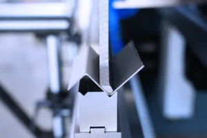
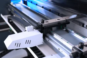
The minimum distance of CNC Press Brake post-regulation distance to the tool, which is often said, the safe positioning distance is generally 10mm. Our general adjustment method is to set the X-axis origin of the above tool tip setting to 10, and then continue to correspond to the upper mold. The distance between the center of the slot of the lower die and the stop point of the back gauge is adjusted to 10 mm, measured with a measuring tool, if there is an error, the machine protection setting is manually fine-tuned to 10 mm.
However, we usually raise the backer by 0.5 mm higher than the lower abrasive tool during processing, so that the CNC Press Brake will not be hit by the mold. After raising it, we can continue to enter 5mm, that is, the minimum distance you ask is 5mm (The thickness of the board is 1.2mm or less) The range of the back gauge is between 20-500, and the bending die is half of the knife edge opening.
How to retrofit NC Press Brake?
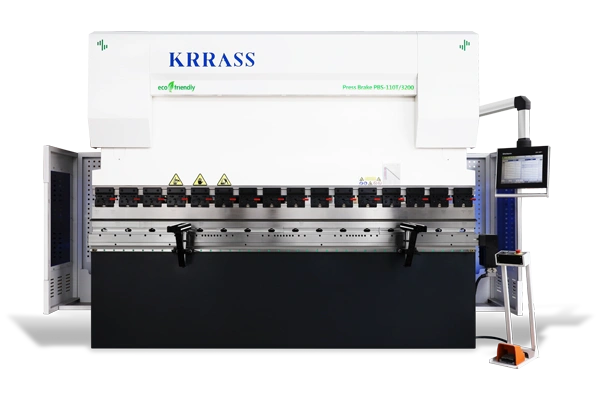
Under today's production conditions, the ordinary Press Brake greatly affects production efficiency, and NC Press Brake cannot meet the accuracy required by existing products; if a company adds a new CNC Press Brake, it will increase the burden on the company, and NC Press Brake will be eliminated. It is also a waste. And we only need to transform the NC Press Brake technically to improve the production efficiency and bending accuracy of the Press Brake.
Technical requirements for transforming NC Press Brake:
- Electrical part: CNC system: add CNC system E300 + suspension arm. Servo system: replace the original ordinary three-phase asynchronous motor drive with a servo drive motor. Electric control box: If permitted by the original electric box, add 2 sets of servo drives, circuit breakers, and intermediate relays inside the electric box. You can also re-configure a small electric box, and make an independent electric box with the added components as needed. As long as the power is drawn from the middle electric box, the added digital control input and output signals and the newly configured electric box signals are exchanged. Can.
- Mechanical part: The part of the back gauge is installed with the servo motor to process the transition piece (the installation size of the ordinary motor is different from the size of the ESTUN servo motor that needs to be replaced, and it needs to be reprocessed) to reduce the error.
- Hydraulic system: retain the original hydraulic system, and the newly added CNC system can flexibly assemble the output control of the original machine tool valve group
Learn more about our products, please visit and subscribe to our Youtube channel
