Pagination:
Part.I
Part.II
Part.III
Part.IV
Table of Contents
1 Interface Display
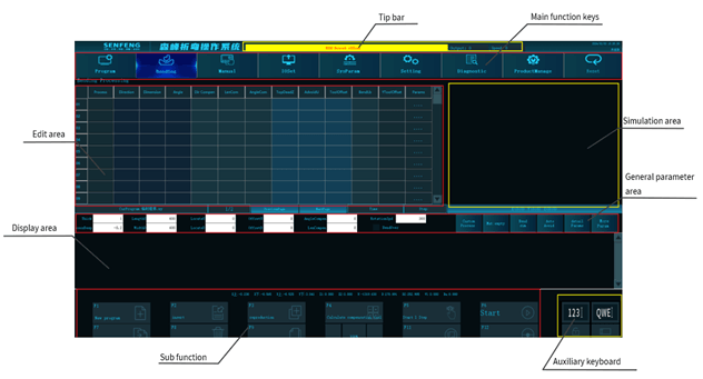
1.1 Main Function Keys

It is the program management key. Click to enter the program management interface, where you can control the program or use sub-function keys to create a directory, create a program, copy, zoom the drawing, uninstall the U disk, enter to confirm, delete the directory, delete the program, paste, NC, USB, NET, etc..

It is the bending processing key. Click to enter the corresponding interface. You can set processing parameters or use sub-functions to clear, insert, delete, start from step 1, run (pause), save as, run speed adjustment, software pedal, handwheel simulation , etc..

It is a manual control key. Click to enter the corresponding interface, and you can choose handwheel or manual mode to quickly move the corresponding axis.

It is the IO input and output key. Click to enter the corresponding interface. You can use the sub-function keys to perform operations such as lubricating oil, pressing the knife or releasing it, closing the brush plate to the left, and closing the brush plate to the right, etc..

It is the production management key. Click to enter the corresponding interface to view the current bending program, bending time of single piece, total bending time, bending quantity, total bending output, and target output.
1.2 Auxiliary Keyboard Description

This is the numeric auxiliary keyboard.

This is the alphabetic auxiliary keyboard.

This is the unlock key.
2 Program Management
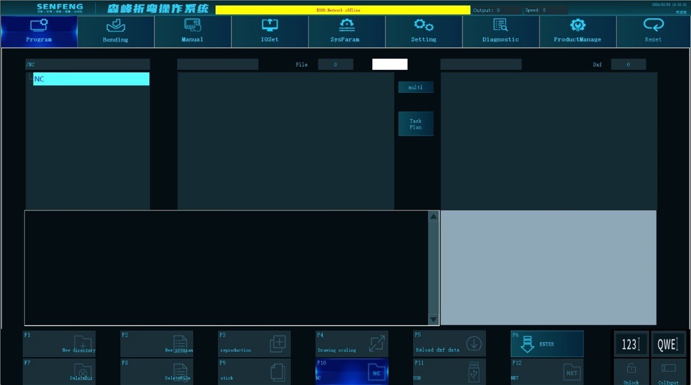
2.1 Program Management Introductions
NC: Displays the file directory in the control system.
File: Displays the direct programming file (.xy).
DXF: Displays DXF programming file (.dxf).
Multiple options: Select multiple bending programming files.
Task plan: Develop multiple bending program bending sequences.
2.2 Sub-function Description
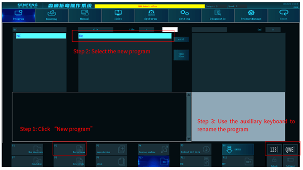
2.2.1 Create a New Directory or a New Program
Save the new directory created through the sub-function in the system in the format of dir, dir2, dir3…
Save the new program created through the sub-function in the system in the format of file,file2,file3… (.xy)
Steps:
- Create a new directory or a new program. Click the corresponding sub-function button of “New Directory” or “New Program”.
- Select the newly created directory or newly created program.
- The new directory or new program can be renamed through the numeric or alphabetic auxiliary keyboard.
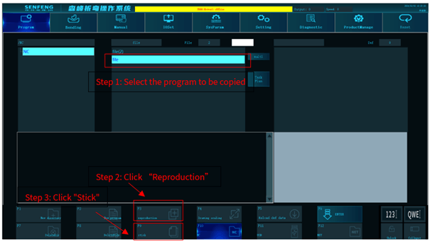
2.2.2 Copy and Paste
Copy the selected directory or program file, and paste it to the corresponding location.
Steps:
- Select the program or directory to be copied.
- Click the sub-function key “Reproduction”.
- Click the sub-function key “Stick” to paste the program or directory to be copied to the corresponding location and save it.
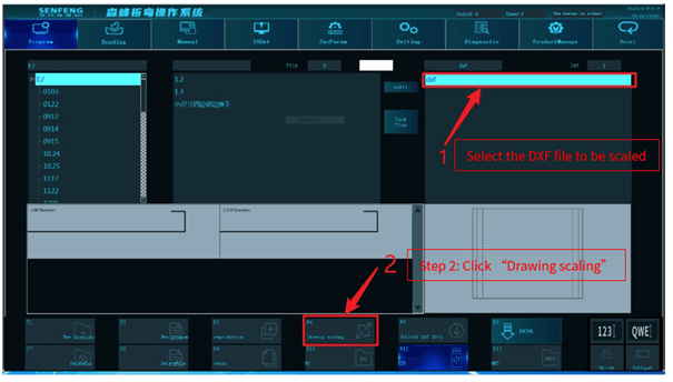
2.2.3 Scale the Engineering Drawing
Scale the selected diagrams of DXF files
Steps:
- Select the DXF file to be scaled.
- Click the sub-function ” Drawing Scaling” button, and the system will display the drawing in full screen.
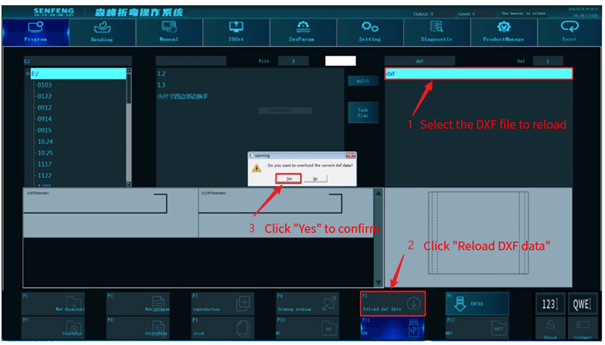
2.2.4 Reload DXF data
Click this function to reload the current DXF data.
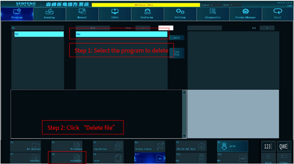
2.2.5 Delete the Directory or Program
Delete the selected directory or program.
Steps:
- Select the directory or program to be deleted.
- Click the corresponding sub-function of “Delete Directory” or “Delete File”.
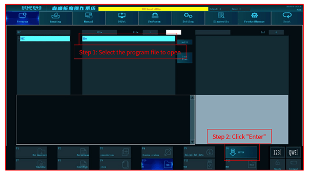
2.2.6 ENTER
Open the selected program directory, program file, and DXF graphics.
Steps:
- Select the program directory or program file or DXF graphics to be opened.
- Click the sub-function button “ENTER” to open them.
2.2.7 NC
Display the control system directory.
2.2.8 USB
Display the USB directory (after inserting USB, the system will display its directory).
