Pagination:
Part.I
Part.II
Part.III
Part.IV
Table of Contents
4 Manual Control
It can display the machine tool coordinate value, the upper tool working coordinate value, and the lower tool working coordinate value (the upper and lower tool workpiece coordinates can be switched through sub-function keys).
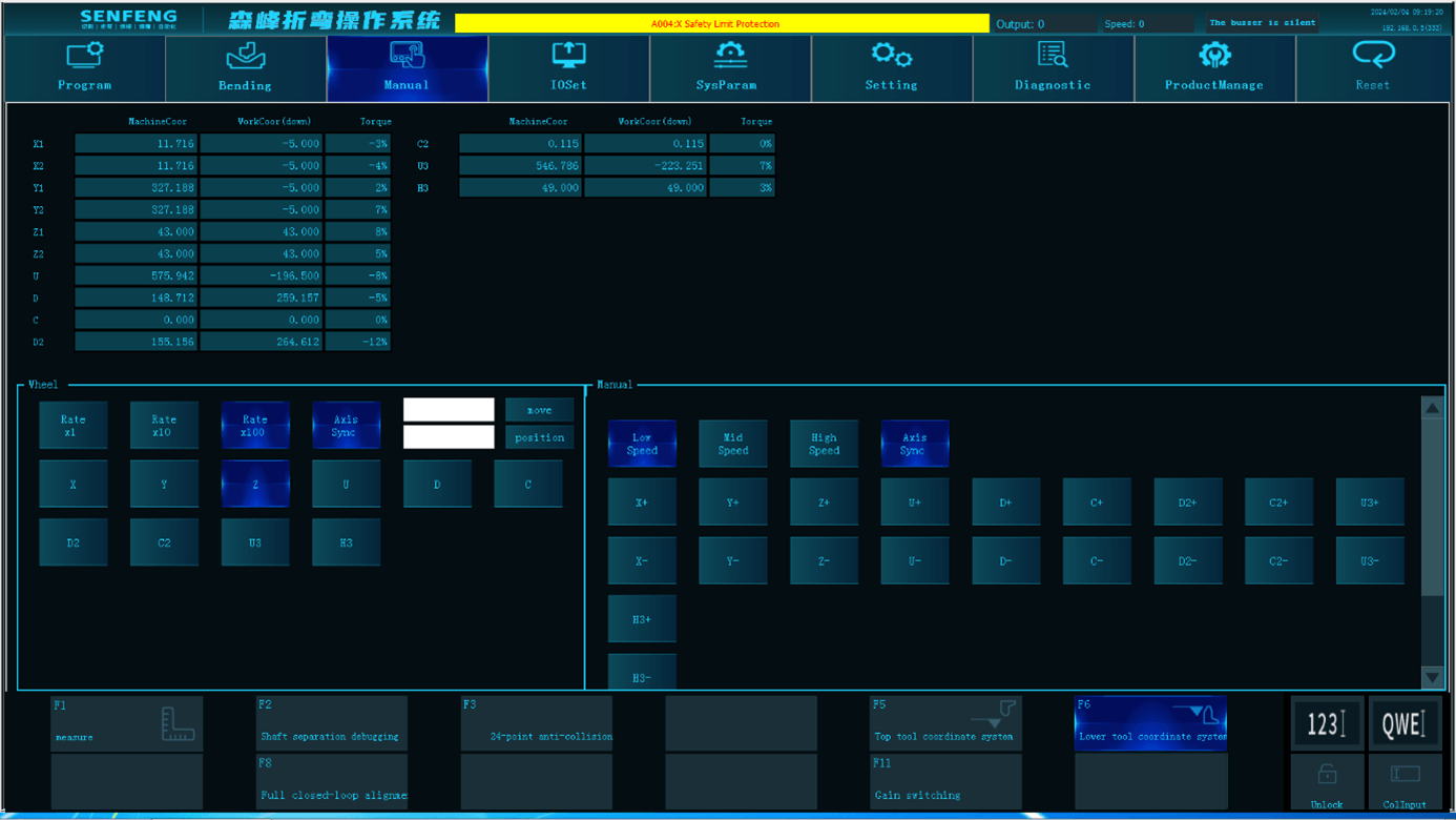
4.1 Handwheel Description

The handwheel mode has three gears: x1, x10, and x100. You can select the corresponding axis through function keys or switch the handwheel speed through the gear of the external electronic handwheel. Select the axis that needs to be controlled through the rotary switch of the external electronic handwheel, and then rotate the handwheel forward and backward to move the corresponding axis.
For example: Use the electronic handwheel to move the X-axis in the forward direction at hand speed.
Note: This mode is mainly used for tool setting. After entering this mode, you can set or clear the X, Y, Z, D, D2, U, U3, H3, C, and C2 axes. The system will automatically save the current working coordinates.
Steps:
- Set in manual control mode.
- Select the moving axis and turn the axis selection knob on the electronic handwheel to the X position.
NOTE: Use the axis selection knob to select the axis to move.
- Select the moving speed and turn the speed magnification knob to the x10 position.
Note: You can use this knob combined with the turning speed of the hand crank to change the moving speed.
- Turn the electronic handwheel clockwise, and the X-axis moves in the positive direction.
Note:
- Rock the hand crank counterclockwise to move the X-axis in the negative direction.
- When the movement speed is x1, the movement amount of each hand crank rotation is 0.001mm. When x10 is selected, the movement amount per shake is 0.01mm, and so on.
4.2 Manual Instructions
The manual mode has three gears: low speed, medium speed and high speed. You can press the corresponding axis acceleration and deceleration keys to move it up and down.
5 IO Input and Output
5.1 Sub-function Description
5.1.1 Output Function
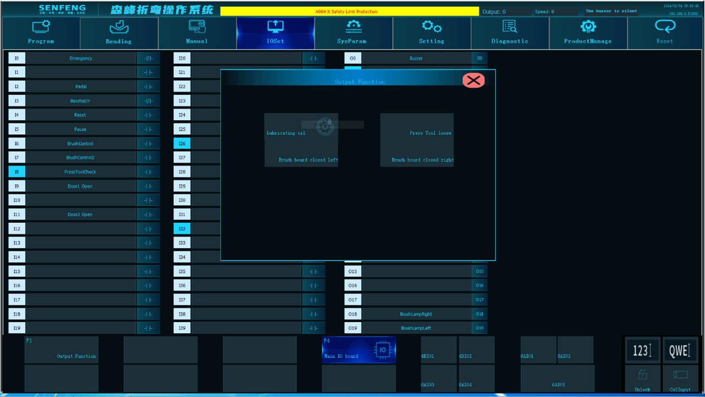
Lubricating oil: Force the oil pump to supply oil.
Press tool loose: Control the locking and loosening of the upper press knife.
Brush board closed left: Control the lifting of the brush plate on the left side.
Brush board closed right: Control the lifting of the brush plate on the right side.
6 Setting
6.1 System Information
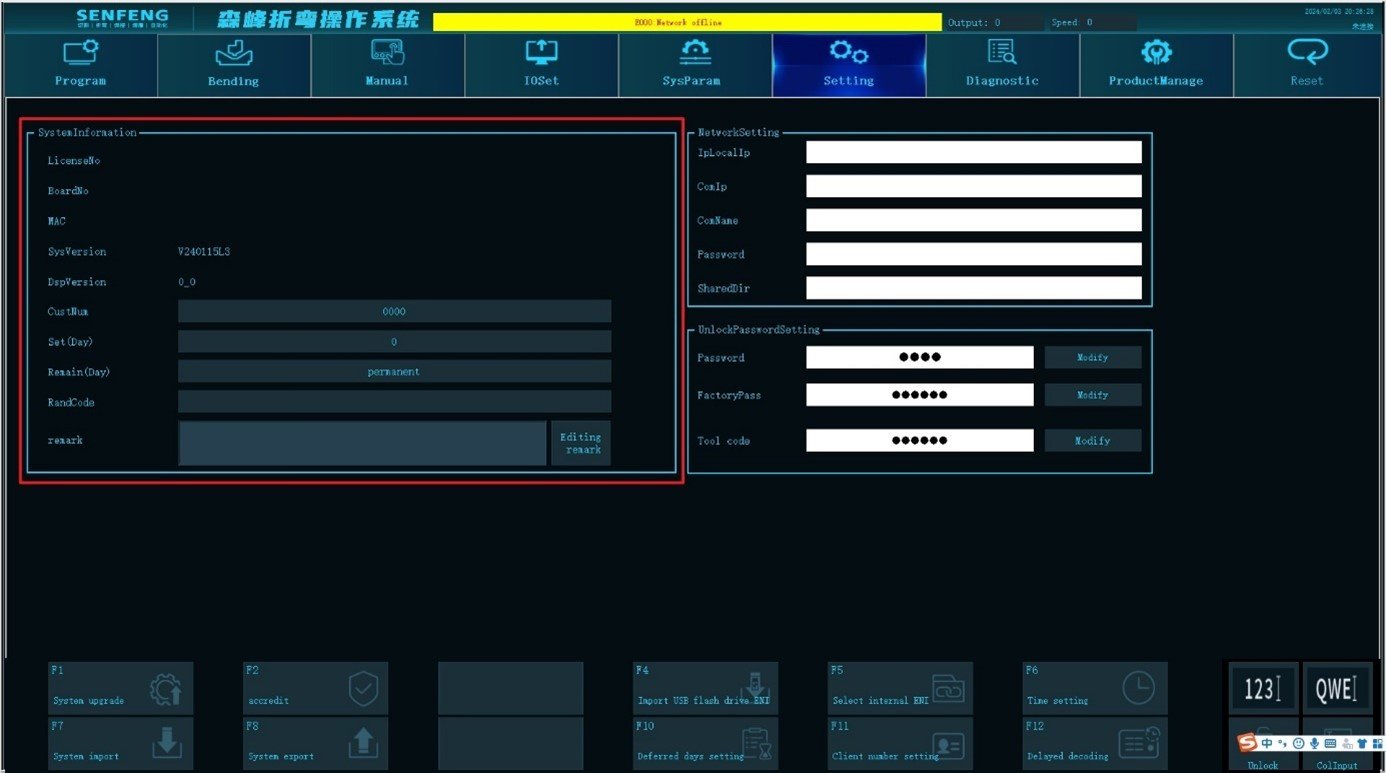
In the system information area, you can view the authorization number, system version, DSP version, system setting cycle, remaining time and other information.
6.2 Unlock Password Settings
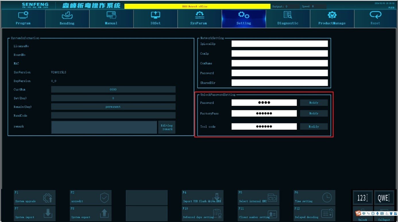
Password: User password can be modified after unlocking
6.3 Sub-function
6.3.1 Extension Decoding
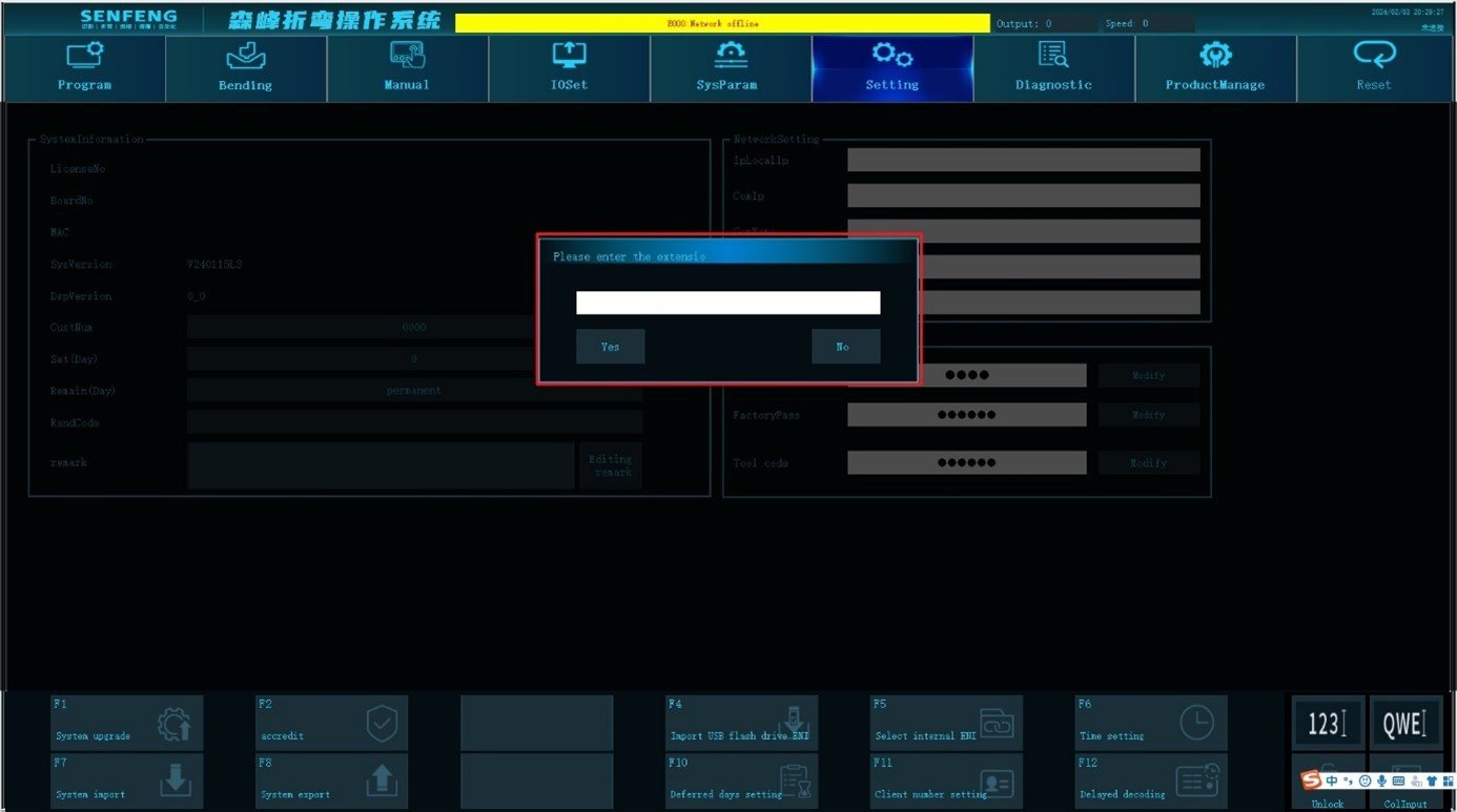
Function description: Unlock the device after locking it.
Steps:
- Contact our company to obtain the extension password.
- Click the sub-function "Extension Decoding" button, and the system will pop up the "Please enter the extension password" dialog box.
- Enter the password in the dialog box and click Yes.
7 Production Management
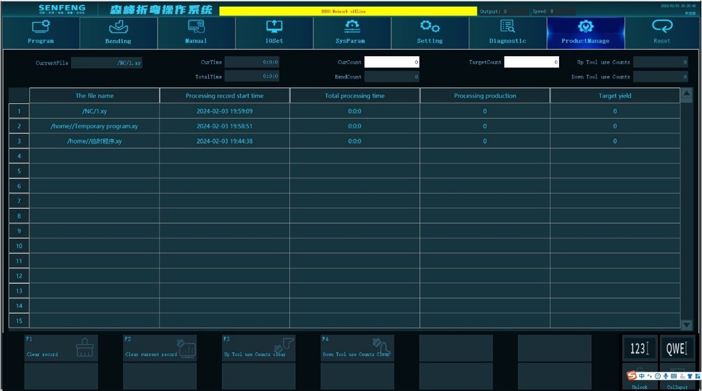
Current file: Display the direct programming file (.xy).
Current time: The time required to produce one product.
Total time: The time it takes for all products to be completed.
Current count: The quantity of finished products.
Bend count: The total number of finished products
Target count: The quantity of products that need to be bent, greater than or equal to 0 (invalid when set to 0).
Up tool use count: The number of times the upper bending knife is used.
Down tool use count: The number of times the lower bending knife is used.

