In the previous article, we introduced how to do reference point check for DA-58T CNC press brake. Delem controller is an excellent CNC press brake controller, which is being chosen and used by more and more manufacturers. However, most users cannot accurately correct the bending work when using it. Today, we will teach you how to use Delem DA-58T CNC press brake for bending and correction.
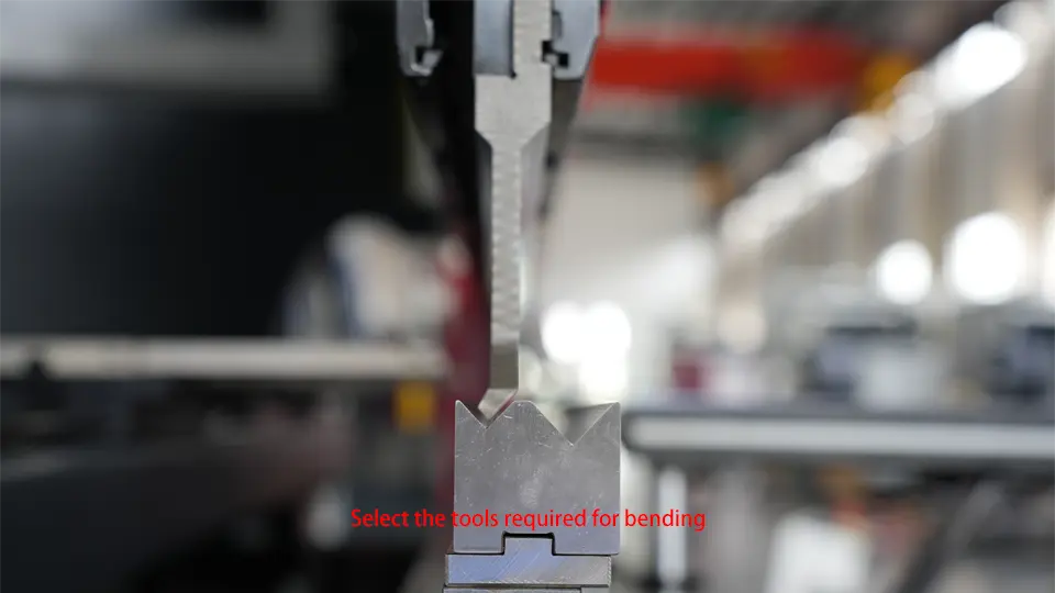
1. Measuring Sheet and Selet Mold
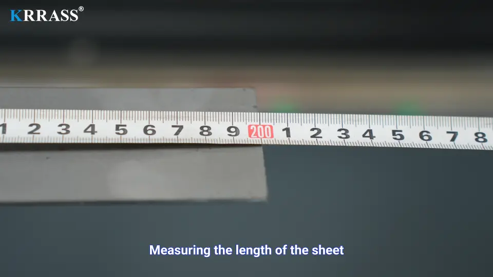
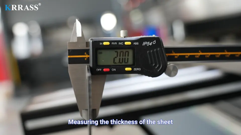
Before we bend the workpiece, we need to measure the length and thickness of the plate in sequence; at the same time, according to our production needs, install tools suitable for the production of the workpiece, and add the parameters of the relevant tools to the DA-58T controller.
2. Programming Control
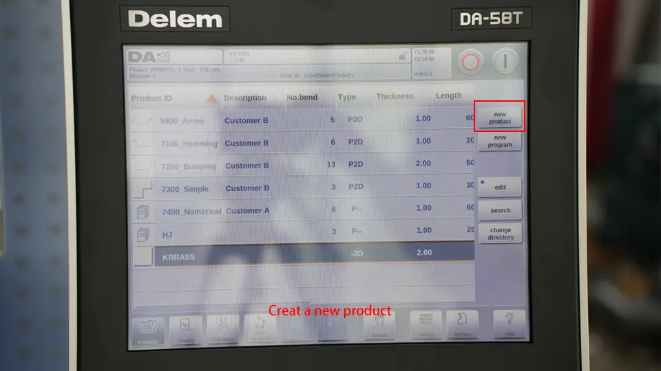
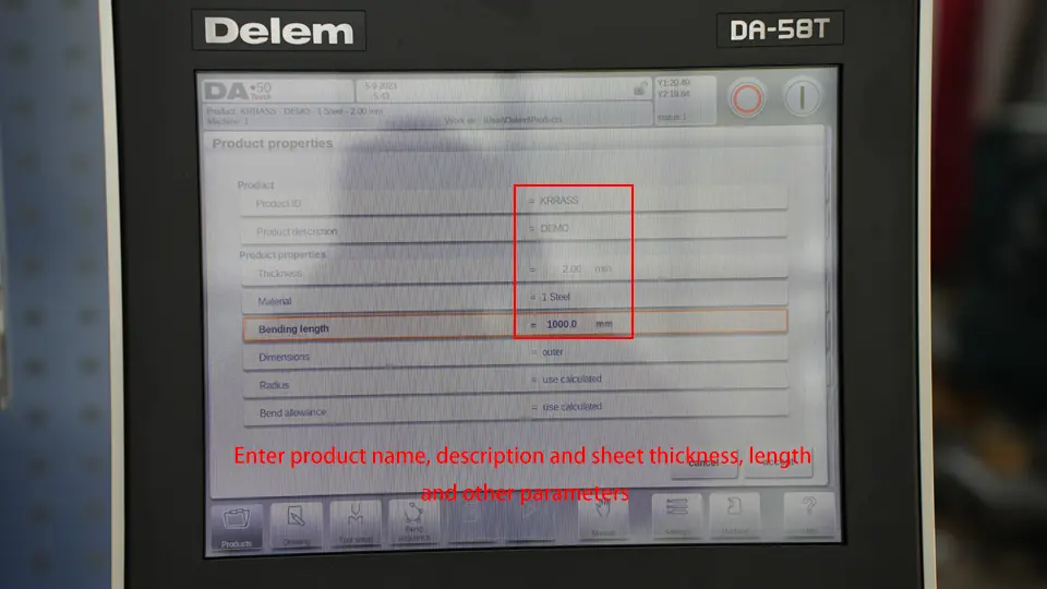
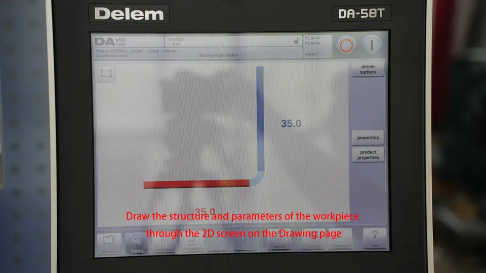
Use the DA-58T controller to create a new bending program, input the relevant parameters of the plate in sequence, select the corresponding mold, and finally input the specific parameters of the bending process;
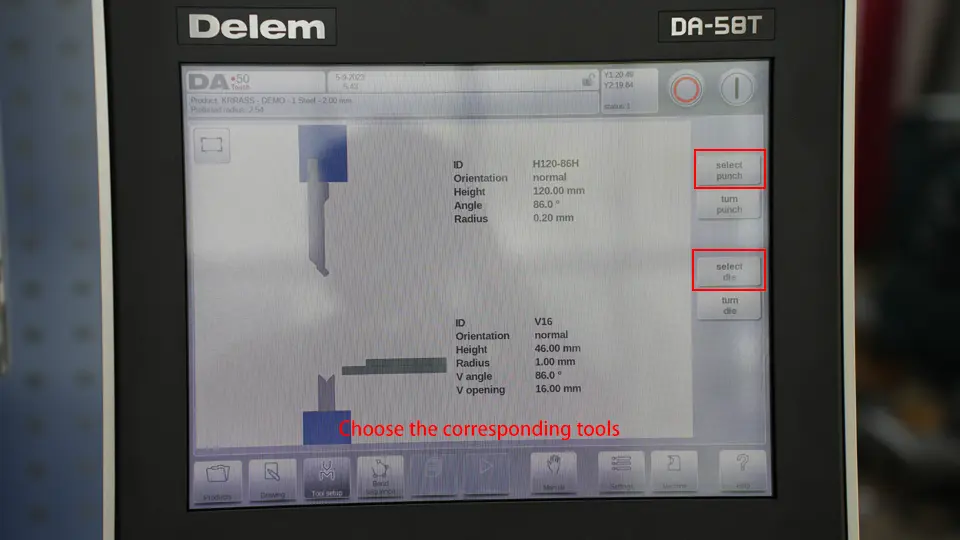
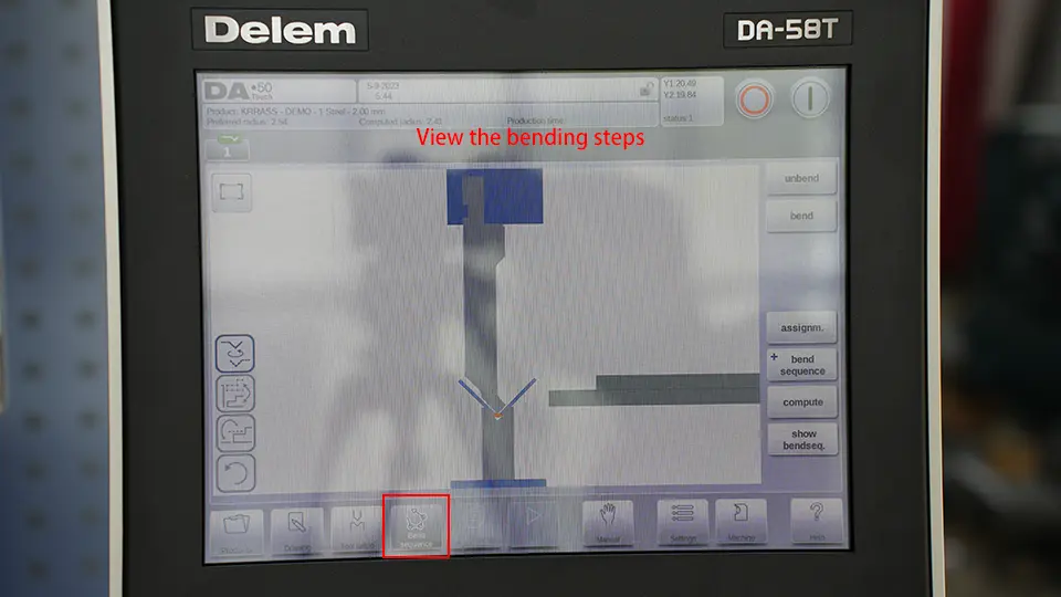
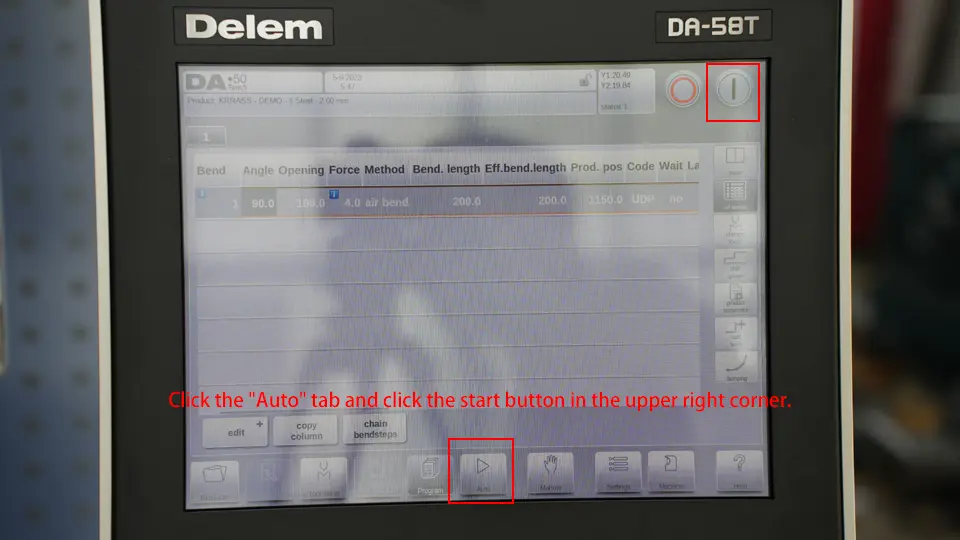
3. Sheet Bending Test
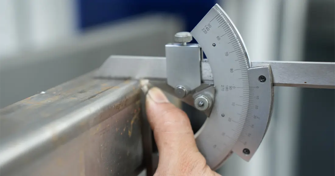
Put in the plate, pre-bend the plate, and then take out the plate to measure the bending accuracy. We marked the left, middle, and right positions of the plate as ①, ②, and ③ in sequence, and the measured values are as follows:
- ① Position: 90°30′
- ② Position: 89°20′
- ③ Position: 89°10′
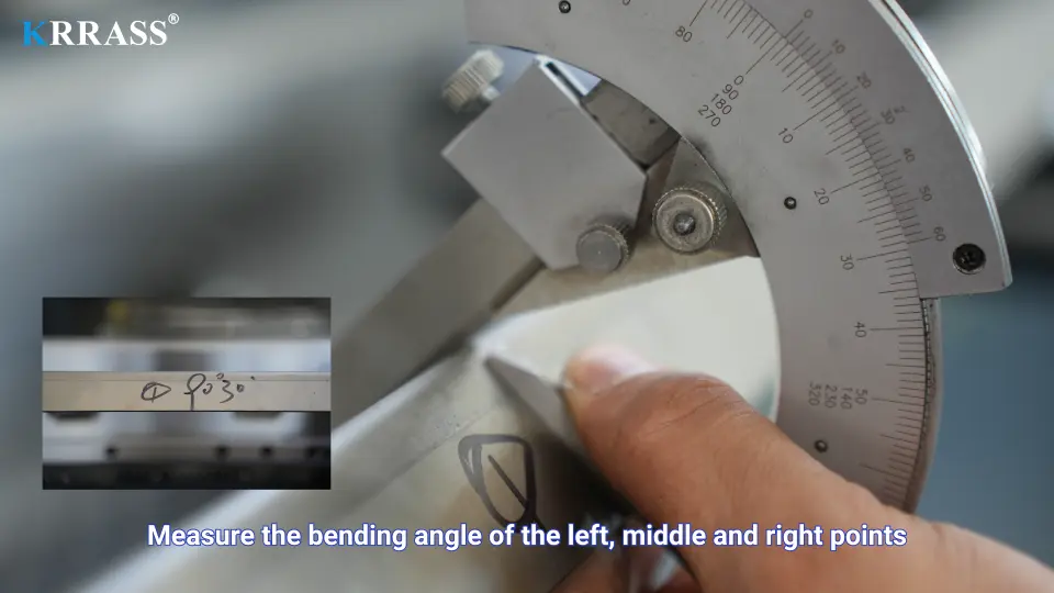
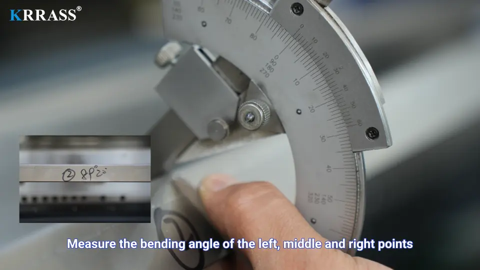
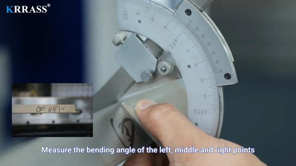
We can see that the angles of positions ② and ③ have not reached our expected value, and we need to correct them;
4. Y-axis Correction
To correct the bending deviation angle, we must first correct the Y axis, that is, the two ends of the bent workpiece. From the previous stage data, we can see:
- The angle of position ① corresponding to the Y1 axis is 90°30′, which basically meets our needs and does not need to be corrected;
- The angle of position ③ corresponding to the Y2 axis is 89°10′, the deviation is large and needs to be corrected;
The specific correction method is as follows. In the “Corrections” area on the right side of the controller work page, find the “Corr. The value is a positive value; if the actual bending angle is greater than the expected angle, the compensation value is a negative value), and the compensation value is the difference between the actual bending angle and the expected angle.
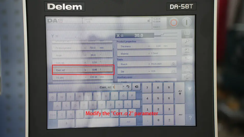
After passing the Y-axis correction, we measure the folded plate again, and measure the values of ①, ②, and ③ respectively as follows:
- ① Position: 90°
- ② Position: 88°40′
- ③ Position: 90°30′
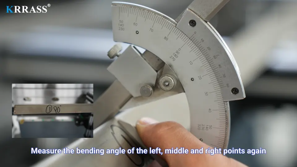
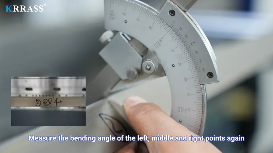
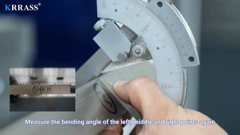
According to the above data, the bending angles of positions ① and ③ on the left and right sides have reached the expected value, but the bending angle of the middle part still needs to be corrected. Let’s continue to see how to perform mechanical compensation;
5. Mechanical Compensation
The method of using the DA-58T controller for mechanical compensation operation is as follows. In the “General corrections” area on the right side of the controller work page, find the “deflect” parameter and set its compensation value. The calculation formula of specific compensation parameters is as follows:
D (compensation parameter) = V (lower die groove width mm) / 2*N (compensation angle)
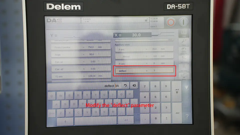
Note: The value of the compensation angle can be positive or negative.
- When the actual bending angle is greater than the expected angle, it is necessary to increase the compensation, which is a positive value at this time;
- When the actual bending angle is smaller than the expected angle, the compensation needs to be reduced, and it is a negative value at this time.
That is: the width of the die used for bending this time is 16mm, and the deviation angle is close to -2 degrees, then the value of the compensation parameter is: 16/2*-2=-16, we can set its value in the “deflect” parameter Set it to -15, and bend again;
6. The result, confirm the completion
Through the above correction operation, we finally get the bending result as follows:
- ① Position: 90°50′
- ② Position: 90°18′
- ③ Position: 90°30′
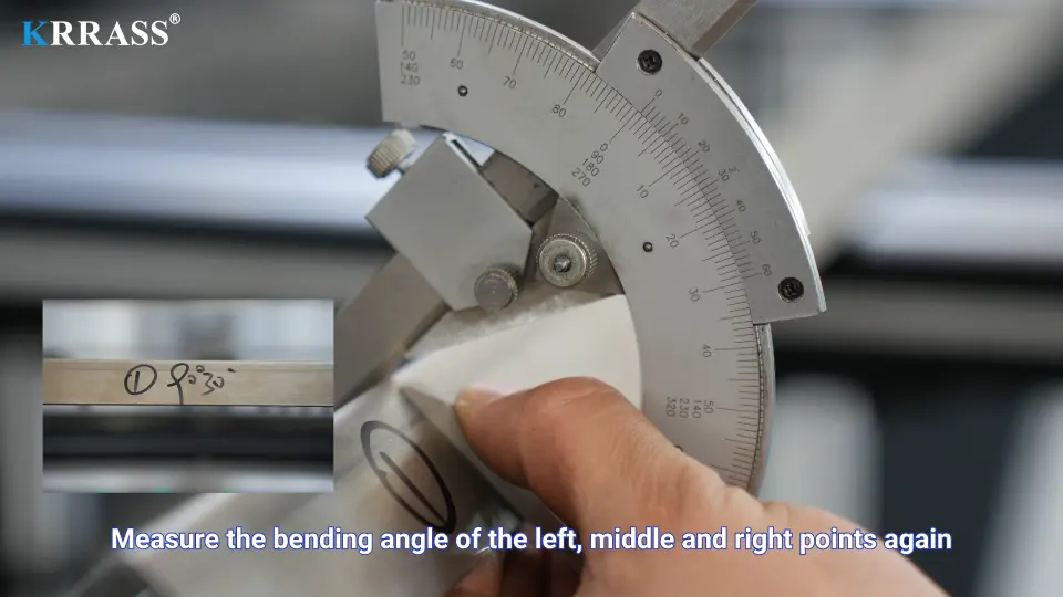
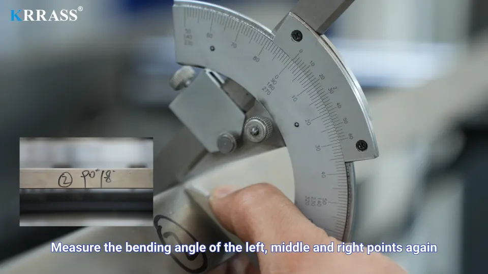
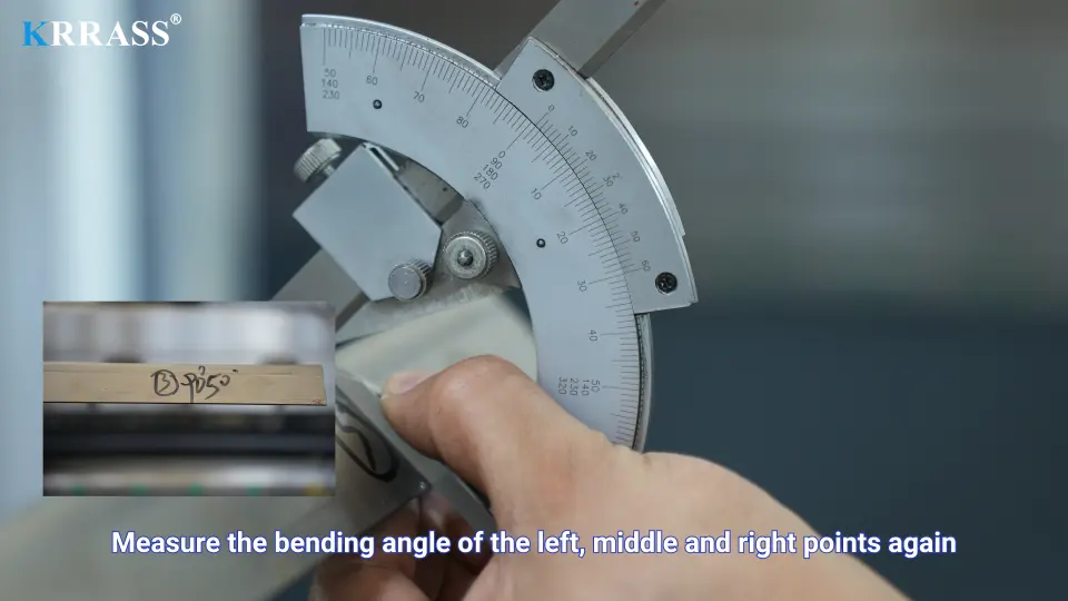
This result has met our bending requirements and reached the expected value.
The above is the specific process and method of how to use Delem DA-58T CNC press brake for bending and correction operations. If you want to have a deeper understanding of DA-58T CNC press brake, you can check our following tutorial content:
- DELEM DA58T CNC press brake installation-I
- DELEM DA58T CNC press brake installation(Tool configuration) – II
- DELEM DA58T CNC Press Brake (finding reference point) – III
