In the intricate world of metal fabrication, where raw materials are transformed into the functional components that underpin our modern lives, few machines hold as central a role as the press brake. Look around you – the crisp angles on electronic enclosures, the sturdy framework of vehicles, the structural elements of buildings – many owe their form to the precise power of this remarkable device.
It is the unsung hero behind countless everyday objects and critical industrial parts, enabling manufacturers to bend and shape flat sheets of metal into complex, three-dimensional structures with accuracy and efficiency. This exploration delves into the fundamentals of press brake work, examining its core principles, operational methods, key components, and wide-ranging applications, revealing why it stays an indispensable cornerstone of manufacturing worldwide.
Table of Contents
Introduction to Press Brakes
Definition and Significance
A press brake stands as a powerful and indispensable machine in the realm of metalworking, specifically designed for bending and shaping metal sheets and plates. This is achieved by the application of significant force onto a workpiece that is positioned between a punch, which is the upper tool, and a die, the lower counterpart .
This fundamental process allows for the creation of precise bend angles and intricate shapes, making the press break a cornerstone of modern metal fabrication across a multitude of industries . The operation fundamentally involves securing the metal sheet between the punch, typically mounted on a moving part called the ram, and the die, which is usually stationary. Subsequently, a controlled force is exerted, leading to the deformation of the material into the desired configuration .
The journey of metal bending has evolved considerably from manual techniques to highly automated processes. This evolution underscores the increasing demand within manufacturing for components with enhanced precision, improved efficiency in production, and the ability to realize increasingly complex geometric designs. Early methods of shaping metal were labor-intensive and often lacked the consistency needed for modern applications. The advent of the press brake, particularly its modern iterations with sophisticated control systems, has addressed these limitations, providing a reliable and repeatable method for forming metal into a vast array of products.
Historical Context (Brief)
The conceptual origins of the press brake can be traced back to the 19th century, with the invention of the cornice brake in 1882 marking a significant early development in mechanized metal bending . This manually ran tool enabled the clamping of sheet metal and its bending along a straight line, being a notable advancement over earlier, more rudimentary techniques. The first formal recognition of the term "press brake" occurred with the granting of a patent in 1927 to the Cincinnati Shaper Company . This pivotal moment signified a definitive shift towards using mechanical power to achieve more consistent and efficient metal bending.
Understanding this historical progression provides valuable context for appreciating the current level of sophistication in press brake technology and offers insights into potential future developments. The trajectory from manually run tools to computer-controlled machines illustrates a continuous pursuit of improvements in speed, accuracy, and versatility within the metal fabrication industry. This suggests that future innovations will likely concentrate on areas such as further automation, the integration of artificial intelligence, and enhancements in material handling capabilities to meet the evolving demands of manufacturing.
The Fundamental Principle of Press Brake Work
The Punch and Die System
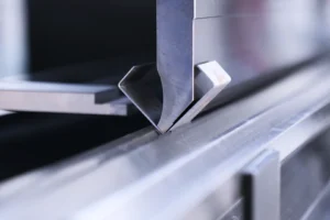
At the heart of a press brake's functionality lies its tooling, which forms an upper punch and a lower die . The punch is typically mounted on the ram, the moving part of the machine, while the die is situated on the bed, the stable base of the press brake . These tools are not standardized but are available in a wide array of shapes and sizes.
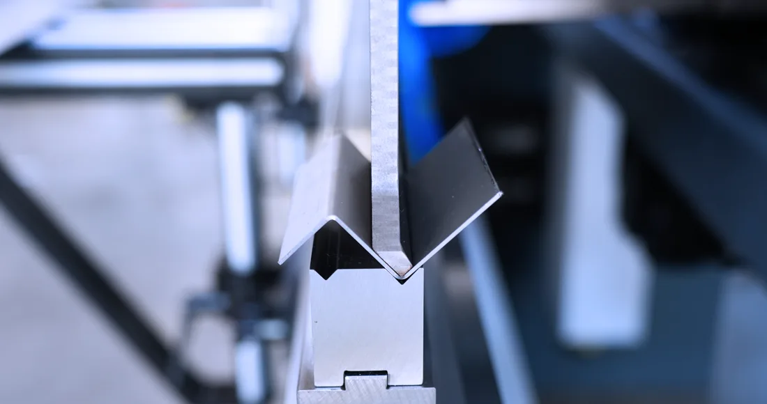
This variety allows the press brake to be adapted to numerous bending requirements, accommodating different angles and intricate shapes as needed for specific manufacturing tasks . A common feature of the die is a V-shaped groove, which plays a crucial role in easing the bending process by providing a defined space for the metal to deform into .
The interchangeability of punches and dies is a key aspect of press brake operation, offering significant versatility. This capability allows a single press brake to perform a broad spectrum of bending operations by simply swapping out the tooling to match the specific requirements of a job. Different product designs often need unique bend profiles, and the ease with which tooling can be changed means that manufacturers can adapt to varying production needs without the necessity of investing in multiple specialized machines. This adaptability is crucial in industries where product designs may change often or where a wide variety of parts are produced.
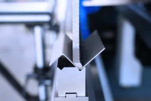
The Bending Process
The process of bending metal using a press brake begins with the precise positioning of the metal sheet on the machine's bed. This is often conducted using a back gauge, an adjustable stop that ensures the metal is placed accurately so that the bend line aligns correctly with the tooling . Once the metal is positioned, the ram, which is driven by a power source that can be hydraulic, pneumatic, or electric, starts its downward movement .
This motion forces the punch to press against the metal sheet, driving it into the cavity of the die . The force exerted during this process causes the metal to undergo plastic deformation, meaning it permanently changes shape to conform to the profile defined by the punch and die . After the desired bend angle has been achieved, the ram retracts to its first position, and the now-bent workpiece can be safely removed from the press brake .
The accuracy of the bend is critically dependent on the precise control of the ram's movement and the correct positioning of the workpiece. Even slight deviations in the depth to which the ram descends or any misalignment of the workpiece can lead to inconsistencies in the final bend angle and the overall dimensions of the part. This highlights the importance of sophisticated control systems that govern the ram's movement and the reliability of the back gauge system in ensuring that each bend meets the required specifications. Modern press brakes often incorporate advanced sensors and feedback mechanisms to check and adjust these parameters in real-time, further enhancing the accuracy and repeatability of the bending process.
Key Components and Their Functions
The operation of a press brake relies on the coordinated function of several key components:
- Frame: This serves as the fundamental structural element of the press brake, providing the necessary support and stability to withstand the significant forces generated during the bending process . A robust frame minimizes vibrations and ensures that the applied force is effectively directed to the workpiece.
- Bed: Found at the base of the machine, the bed is a flat surface on which the metal sheet rests during the bending operation . It often features a V-shaped groove to aid in aligning the workpiece and easing various bending applications .
- Ram: This is the moving upper beam of the press brake that holds the punch. It is responsible for moving downwards and applying the force required to deform the metal sheet against the die . The precision of the ram's movement is crucial for achieving correct bends.
- Punch: As the upper tool, the punch is mounted on the ram and is the part that directly contacts the metal sheet, forcing it into the die to achieve the desired shape . Punches come in a variety of shapes and sizes to suit different bending requirements.
- Die: Positioned on the bed, the die is the lower tool that provides the necessary counterforce to the punch . It plays a vital role in deciding the final shape of the bent metal. Like punches, dies are available in diverse profiles to achieve varied bend angles and shapes.
- Back gauge: This is a critical part for ensuring precision and consistency in bending. It is an adjustable stop that is positioned before the bending process to accurately find the metal sheet, thereby ensuring uniformity in the final product . Modern CNC press brakes often feature back gauges with multiple axes of movement for increased complexity in bending operations .
Each of these components is integral to the overall bending process, and their proper design and maintenance are essential for ensuring correct and reliable operation. A stable frame, a level bed, precise ram movement, and a dependable back gauge all contribute to the quality of the final bent part. Any malfunction or deficiency in these components can negatively affect the accuracy and consistency of the bending process, underscoring the importance of their integrity.
Types of Press Brake Bending
Air Bending

Air bending stands as the most prevalent method employed in metalworking using a press brake. In this technique, the punch presses the metal into the die without making full contact with the bottom of the die cavity . The angle of the resulting bend is primarily decided by the depth to which the punch penetrates the die . A significant advantage of air bending is that it requires less force, or tonnage, compared to other bending methods, making it suitable for a wider range of press brakes and materials .
However, a characteristic of air bending is the potential for spring back, where the material slightly reverts towards its original shape after the bending force is removed. This needs careful calculation and adjustment of the bend angle during the process to compensate for this movement . Often, dies used in air bending have a V-angle that is smaller than the desired final bend angle to account for this spring back .
Air bending offers a considerable degree of flexibility because different bend angles can be achieved using the same set of tooling simply by varying the stroke depth of the ram. This reduces the need for frequent tool changes, leading to increased efficiency in production and lower tooling costs. The versatility of air bending makes it a preferred choice for various bending requirements across different manufacturing applications.
Bottom Bending (Bottoming)
In the bottom bending, or bottoming, method, the metal sheet is fully pressed into the bottom of the V-shaped die. Unlike air bending, in bottom bending, the angle of the die is typically designed to match the intended bend angle of the workpiece . This method requires a greater amount of force, or tonnage, compared to air bending to ensure the metal conforms to the die's shape .
Like air bending, bottom bending is also susceptible to spring back, where the bent material tends to return slightly towards its original flat state after the pressure is released. To counteract this, the material is often overbent to an angle slightly more acute than the desired final angle, allowing it to spring back to the correct specification . Bottom bending is a widespread practice on older, mechanical press brakes, where the accuracy of the bend is primarily a function of the precision of the tooling rather than the positioning accuracy of the press brake itself .
While bottom bending can provide good accuracy due to the full contact with the die, its higher tonnage requirement and the inherent risk of spring back make it a less favored method compared to air bending for many applications on modern, more sophisticated press brakes. The increased force can lead to greater wear on both the tooling and the machine itself, and the need for precise calculations to compensate for spring back can complicate the process, especially when dealing with materials that have varying properties.
Coining
Coining is a bending method that involves forcing the punch and die together with an exceptionally high amount of tonnage. This extreme pressure causes the metal to undergo permanent deformation, essentially imprinting it with the exact shape of the tooling. A key characteristic of coining is that it effectively cuts spring back due to the immense force applied, which ensures the metal keeps the shape imparted by the punch and die .
However, this benefit comes at the cost of requiring significantly higher tonnage compared to both air bending and bottom bending, typically ranging from three to ten times that of air bending . Coining is primarily employed in scenarios where achieving the highest levels of precision and repeatability are critical, such as in the minting of coins or in the production of components requiring very tight tolerances .
While coining offers unparalleled accuracy and negates the issue of spring back, the substantial force it demands can limit its applicability based on the ability of the press brake and the structural integrity of the tooling. The immense pressure can potentially cause damage to the machine or the tooling if not managed carefully, and it also results in higher energy consumption. Therefore, coining is typically reserved for specific, high-precision applications rather than being used as a general bending method.
Other Bending Techniques (Briefly Mention)
Beyond the three primary methods, several other specialized bending techniques are used in press brake operations:
- Folding: This technique involves clamping the longest section of the metal sheet between clamping beams, after which a bend beam rises and folds the extending part of the sheet around a specific bend profile . Folding is particularly helpful when creating complex parts that require both positive and negative bend angles.
- Three-Point Bending: Considered by some as a specialized variation of air bending, this method uses a unique die where the height of the bottom tool can be precisely adjusted using a servo motor . Three-point bending offers high flexibility and the ability to achieve very precise bend angles, but it can be more expensive and have a limited selection of available tools.
- Rotary Bending: This technique employs a cylindrical-shaped die that has an 88-degree V-notch cut along its axis. The die acts as an anvil over which a rocker bends the sheet metal .
The availability of these diverse bending techniques allows manufacturers to select the most proper method based on the specific requirements of the part being produced, including its design complexity, the properties of the material, and the overall production volume needed. Each technique offers a unique set of trade-offs in terms of accuracy, the force needed, the complexity of tooling, and the speed of the process, enabling optimization for a wide array of manufacturing scenarios.
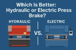
Force Application: Hydraulic, Pneumatic, and Electric Press Brakes
Hydraulic Press Brakes

Hydraulic press brakes are characterized by their use of hydraulic cylinders to generate the force necessary for bending metal . These machines are renowned for their ability to deliver high force, making them particularly well-suited for bending thick and heavy materials that require substantial power to deform . Hydraulic systems also offer a good degree of control over the bending pressure and the speed at which the bending operation is performed . Historically, hydraulic press brakes have been the most common type found in metal fabrication shops due to their reliability and versatility .
Among the advantages of hydraulic press brakes are their high bending force ability, their versatility in managing a wide range of material types and thicknesses, and their established reliability for heavy-duty applications . However, they also have certain disadvantages. Compared to electric or pneumatic types, hydraulic brakes can be slower in operation. They typically need more maintenance due to the complexity of their hydraulic systems, which can involve issues such as fluid leaks, seal replacements, and the need for regular fluid changes. Additionally, the continuous operation of hydraulic pumps can lead to heat generation and higher noise levels, and they are generally considered to be less energy-efficient because the hydraulic pump often runs even when the machine is idle .
Despite these drawbacks, hydraulic press brakes stay a significant presence in the industry due to their robust power and versatility. They are particularly essential for manufacturers who deal with a broad spectrum of material types and thicknesses, especially when working with thicker materials where the high force capabilities of hydraulic systems are crucial. Nevertheless, the increasing emphasis on energy efficiency and the reduction of maintenance overheads are driving a growing interest in and adoption of more energy-efficient alternatives, such as electric press brakes, for applications that do not necessarily require the highest levels of force.
Pneumatic Press Brakes
Pneumatic press brakes use compressed air as the power source to generate the force needed for bending sheet metal . These types of press brakes are typically employed for lighter applications where the tonnage requirements are lower . A key characteristic of pneumatic systems is their high operating speed, which can be helpful in certain production environments . Furthermore, the control of air pressure is generally simpler compared to hydraulic fluid, which can offer some operational benefits .
The advantages of pneumatic press brakes include their high speed of operation, a relatively simple machine setup, and the ease with which the operation can be halted if necessary . For light-duty tasks, they can also be a more economical choice. However, pneumatic brakes have limitations, particularly in terms of the force they can generate, which is significantly less than that of hydraulic and even some electric brakes . This limited power means they are not suitable for bending thick or high-strength materials. Additionally, while they offer high speed, this can sometimes come at the cost of reduced accuracy compared to hydraulic or electric systems .
Pneumatic press brakes are ideally suited for scenarios involving the high-speed, repetitive bending of thinner materials where extreme force is not a prerequisite. This makes them a good fit for specific niche applications within the broader metal fabrication industry. In high-volume production settings dealing with small, thin parts, the speed advantage of pneumatic systems can lead to a notable increase in production throughput. However, their inherent power limitations restrict their applicability in more demanding fabrication tasks that require bending thicker or stronger materials.
Electric (Servo-Electric) Press Brakes
Electric press brakes, also known as servo-electric press brakes, use electric motors to drive servo-controlled mechanisms, such as ball screws or belt drives, to apply the necessary tonnage for bending metal . These machines are notable for offering very precise control over the movement of the ram, which translates to elevated levels of accuracy and repeatability in the bending process . A significant advantage of electric press brakes is their energy efficiency, as they typically consume power only during the actual bending operation, unlike hydraulic systems that may run continuously . They also tend to produce less noise compared to hydraulic brakes and require less maintenance due to the absence of hydraulic fluids and seals that need regular servicing .
The benefits of electric press brakes include their high accuracy and precision, significant energy efficiency leading to lower operational costs, reduced maintenance requirements, quieter operation, and in some cases, faster bending speeds . However, they may also have some drawbacks. The first purchase cost of an electric press brake can be higher compared to a hydraulic machine of similar capacity .
Additionally, while the force capabilities of electric brakes are improving, they may still have a limited force range compared to the largest hydraulic press brakes, although they are well-suited for light to medium duty bending tasks . Continuous operation of electric presses can also generate heat, which may need the use of cooling systems to keep precision and prolong the life of machine components .
Electric press brakes are gaining increasing popularity in the manufacturing sector, particularly for applications that demand high precision, energy efficiency, and a lower environmental impact. They are especially favored for lighter to medium duty bending operations where the extreme force of a large hydraulic press is not needed. As environmental regulations become more stringent and energy costs continue to rise, the advantages of electric brakes in terms of sustainability and operational cost savings are making them an increasingly attractive alternative to traditional hydraulic systems. Furthermore, advancements in electric motor technology are continually expanding the force capabilities of these machines, broadening their range of applications.

Comparison Table of Press Brake Types
To provide a concise overview of the key differences between hydraulic, pneumatic, and electric press brakes, the following table summarizes their main characteristics:
| Feature | Hydraulic | Pneumatic | Electric (Servo-Electric) |
| Force Capacity | High | Low | Medium |
| Speed | Medium | High | High |
| Accuracy | Good | Moderate | Excellent |
| Energy Efficiency | Low | Moderate | High |
| Maintenance | High | Moderate | Low |
| Initial Cost | Moderate | Low | High |
| Noise Level | High | Moderate | Low |
| Environmental Impact | Moderate | Low | Low |
| Application Suitability | Heavy-duty, versatile | Light-duty, high-speed | Precision, light to medium duty |
This comparison highlights the trade-offs between the different power sources, allowing manufacturers to make informed decisions based on their specific needs and priorities. The choice of press brake type should consider factors such as the materials being worked with, the required precision and speed, budget constraints, and environmental considerations.
Understanding Press Brake Tonnage
Definition and Significance of Tonnage
Tonnage, in the context of press brakes, refers to the bending force or the bending ability that the machine can exert on a workpiece . It is typically quantified in units of tons per foot of bending length or kilonewtons per meter . This rating shows the maximum force that the press brake can apply to deform the metal into the desired shape . Selecting a press brake with the correct tonnage is of paramount importance for several reasons. Insufficient tonnage can lead to incomplete or inaccurate bends, as the machine may not be able to exert enough force to properly deform the material.
Conversely, excessive tonnage can result in over-bending, material damage such as cracking or buckling, and even potential damage to the press brake itself and its tooling . Using the proper tonnage ensures that the bending process is correct, adhering to the required specifications for bend angle and dimension, which is especially critical in industries where precision is non-negotiable, such as aerospace and automotive manufacturing . Furthermore, running within the recommended tonnage range helps to extend the lifespan of the tooling components by preventing overload and premature wear .
The concept of tonnage is therefore a critical parameter when selecting the proper press brake and tooling for a specific metal bending task. It directly influences not only the quality of the final product but also the safety and efficiency of the bending operation. Fabricators must carefully consider the material properties, the desired bend geometry, and the capabilities of their machinery to ensure that the selected tonnage is adequate for the job without exceeding the limits of the equipment.
Factors Affecting Tonnage Requirements
The amount of tonnage needed for a specific bending operation is influenced by a variety of factors, including:
- Material Type: Different metals have varying degrees of tensile strength and elasticity, which directly affect the force needed to bend them . For instance, bending stainless steel typically requires more force compared to bending aluminum of the same thickness due to stainless steel's higher tensile strength .
- Material Thickness: As the thickness of the metal increases, so does its resistance to deformation, needing a greater amount of tonnage to achieve the desired bend. The relationship between material thickness and needed force is often exponential; doubling the thickness can quadruple the required force .
- Bend Angle and Radius: The sharpness of the bend angle and the tightness of the bend radius also play a significant role in deciding the required tonnage . Generally, sharper angles and tighter radii demand more force. Additionally, the method of bending employed affects the tonnage; air bending requires the least, followed by bottom bending, and coining requires the most force .
- Bending Length: The length of the bend that needs to be made across the metal sheet is directly proportional to the total tonnage required . A longer bend will require a greater overall force from the press brake.
- Die Opening Width (V-Die): The width of the opening in the lower die (V-die) influences the tonnage needed. A wider opening generally reduces the amount of force needed to bend a material of a given thickness . The best die opening width is often related to the material thickness, with common guidelines suggesting a width of 6 to 12 times the material thickness .
- Tooling Selection: The specific shape and condition of the punch and die used in the bending process can affect how force is distributed across the workpiece, thereby influencing the required tonnage . For example, a punch with a sharper nose might require more force than one with a more gradual radius .
- Bending Method: As previously mentioned, the technique used to bend the metal—whether it is air bending, bottom bending, or coining—has a substantial impact on the tonnage needed. Coining needs significantly higher forces compared to the other two methods .
Given the interplay of these numerous factors, it becomes clear that deciding the proper tonnage for a press brake operation requires careful consideration of the material's characteristics, the desired final shape of the workpiece, and the tooling and bending method employed.
Typical Tonnage Ranges for Different Applications (Examples)
The required tonnage for press brake operations can vary widely depending on the specific application:
- For light-duty tasks, such as bending thin gauge materials, a press brake with a tonnage capacity of around 20 tons might be sufficient .
- General metal fabrication work often requires press brakes in the range of 100 to 300 tons, depending on the thickness and type of material being processed .
- Heavy industrial applications, which involve bending thick plates or manufacturing large structural components, can need press brakes with capacities reaching several hundred or even thousands of tons . Some specialized models are capable of exerting forces up to 3000 tons or more .
This broad range of tonnage abilities underscores the diverse applications of press brakes across various industries, from the production of delicate electronic components to the fabrication of massive structural elements used in construction and infrastructure. The technology has evolved to provide machines capable of handling these widely different requirements, highlighting its adaptability to the scale and demands of modern manufacturing.
Calculating Required Tonnage
To estimate the required bending force for a given operation, various formulas and tonnage charts are available . These tools consider the factors discussed earlier, such as material type and thickness, bend angle, bending length, and die opening width. Many formulas incorporate the material's tensile strength as a key parameter . Tonnage charts provide pre-calculated values for common combinations of materials and thicknesses with standard die openings, offering a quick reference for estimating force requirements . Additionally, numerous online calculators are available that allow users to input specific parameters to decide the estimated tonnage needed for their bending task .

It is important to note that these calculations and charts provide estimations, and it is crucial to consider potential variations in material properties and to incorporate a safety margin when selecting a press brake and planning an operation . A common recommendation is to choose a press brake with a tonnage capacity that exceeds the calculated requirement by 20 to 30 percent to accommodate these variations and ensure safe and effective bending . While these tools offer valuable guidance, the practical experience and understanding of material behavior that skilled operators have are often essential for making correct tonnage estimations and ensuring the safe and successful execution of bending operations.
Precision and Automation: CNC Press Brake Operation
Introduction to CNC Control
The integration of CNC (Computer Numerical Control) systems into press brakes has fundamentally transformed metal bending processes by introducing a high degree of automation and precision . In a CNC press brake, operators can program the desired bending parameters, such as the angle, depth, and sequence of bends, directly into the machine's controller . Once programmed, the CNC system takes over the control of the machine's movements, executing the bending process with remarkable accuracy and consistency . This automation significantly reduces the need for manual adjustments during the bending process, leading to improved efficiency and a higher quality of the final product.
The adoption of CNC technology is a major advancement in press brake operation, enabling the production of complex parts with levels of precision and efficiency that were unattainable with earlier, manually ran machines. Where manual press brakes relied heavily on the skill and experience of the operator, CNC automation minimizes the potential for human error and ensures that each part is bent exactly to the programmed specifications. This capability is particularly crucial in industries where tight tolerances and consistent quality are paramount.
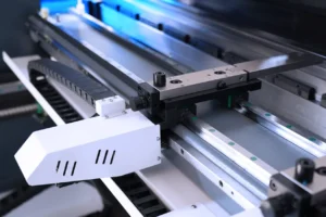
The Role of Back Gauges
A critical part of CNC press brakes is the sophisticated back gauge system, which plays a vital role in ensuring the correct positioning of the workpiece . These systems are capable of moving the metal sheet along multiple axes, typically including the X-axis for forward and backward movement to control the flange length, the R-axis for vertical movement to accommodate different bend heights, and sometimes the Z-axis for left and right lateral movement to allow for more complex part positioning .
In more advanced CNC press brakes, the back gauge system can have up to six axes of control, offering the capability to manage very intricate bending operations . Each axis is independently controlled by the CNC system, allowing for precise and coordinated movements that ensure the workpiece is in the correct position for each bend in a sequence.
The use of multi-axis back gauges significantly enhance the versatility of CNC press brakes. It enables the creation of parts that require multiple bends at very precise locations without the need for manual repositioning of the workpiece between bends. This automation not only reduces the handling time involved in producing complex parts but also improves the overall accuracy of the bending process by cutting the potential for errors that can occur during manual adjustments. The ability to precisely position the workpiece in multiple dimensions allows manufacturers to produce more complex geometries and meet tighter design specifications.
Multiple Axes of Control (Y1, Y2, X, R, Z, etc.)
CNC press brakes use a system of multiple axes to achieve precise and coordinated movements during the bending process:
- The Y1 and Y2 axes are crucial for controlling the vertical movement of the ram. They independently manage the left and right sides of the ram, ensuring that it moves down in a parallel fashion to the bed. This synchronized movement is essential for achieving correct and consistent bend angles across the entire length of the workpiece .
- The X-axis controls the horizontal movement of the back gauge, which is used to decide the flange length of the bent part. By moving the back gauge forward or backward, the CNC system ensures that the workpiece is positioned correctly for each bend .
- The R-axis provides vertical control of the back gauge, allowing it to be raised or lowered. This is particularly useful when bending parts with multiple flanges or when different bend heights are required .
- The Z-axis (and sometimes added Z1 and Z2 axes) controls the lateral movement of the back gauge fingers. This allows for the precise positioning of the workpiece from side to side, which is necessary for certain complex bending operations .
- In addition to these primary axes, some advanced CNC press brakes may include other axes to control parameters such as the crowning system, which compensates for machine deflection, or for automated material handling systems.
The precise and coordinated movement of these multiple axes, all under the control of the CNC system, enables the creation of overly complex and correct three-dimensional parts from flat sheets of metal. This level of control allows for intricate bending sequences and geometries that would be extremely difficult, if not impossible, to achieve using manual methods.
Benefits of CNC Operation

The implementation of CNC technology in press brakes offers numerous benefits to manufacturers:
- Increased Precision: CNC machines can achieve extremely elevated levels of accuracy in bending, often within millimeters or even microns of the programmed specifications . This precision is essential for producing parts that meet stringent quality standards and tight tolerances.
- Enhanced Repeatability: Once a bending program has been set up, a CNC press brake can consistently produce identical parts, time after time . This repeatability is crucial for mass production and ensures that all parts in a batch are uniform.
- Improved Efficiency: By automating much of the bending process, CNC machines reduce the need for manual labor, minimize setup times for new jobs, and decrease the amount of material wasted due to errors . This leads to higher productivity and lower overall manufacturing costs.
- Greater Complexity: CNC control allows for the creation of intricate shapes and the execution of multiple bends in a single operation . This capability opens possibilities for more complex part designs that might be challenging or impossible to produce with manual equipment.
- Ease of Use: Modern CNC systems are often equipped with user-friendly interfaces and intuitive programming software . This makes it easier for operators to program and run even complex bending jobs, reducing the learning curve and improving overall operational efficiency.
In conclusion, CNC press brakes provide a significant competitive edge in the manufacturing industry by offering the ability to produce higher quality parts more quickly and efficiently, while also enabling the fabrication of more complex and innovative designs. The precision and automation afforded by CNC technology are essential for meeting the demands of modern manufacturing and staying competitive in the global market.
Ensuring Accuracy Across the Length: The Crowning System
The Problem of Machine Deflection
During the metal bending process in a press brake, the immense forces applied can cause the machine's structural components, specifically the ram (upper beam) and the bed (lower table), to flex or deflect . This deflection is particularly pronounced towards the center of the machine, where the bending force is often concentrated, and the supports are furthest away .
The result of this flexing is an uneven bend in the workpiece, where the angle in the center tends to be more open than at the ends, where the ram and bed are more rigidly supported by the machine's frame . The severity of this crowning effect is worsened when dealing with longer workpieces, as the flexing forces are distributed over a greater distance, and when higher bending forces are needed for thicker or stronger materials .
Machine deflection is an inherent challenge in press brake operation, especially for larger machines and more demanding bending tasks. If not addressed, this phenomenon can significantly compromise the accuracy and consistency of the final bent part, leading to products that do not meet the required specifications. Therefore, a method to counteract this deflection is crucial for achieving high-quality bending results.
The Purpose and Importance of Crowning
To overcome the issue of machine deflection, press brakes are often equipped with a crowning system . The primary purpose of this system is to compensate for the natural bending or bowing that occurs in the ram and bed during the application of bending force. By counteracting this deflection, crowning ensures that the bend angle stays correct and uniform across the entire length of the workpiece . The crowning system typically works by applying an opposing force or creating a slight curvature in the bed or ram that is opposite to the deflection caused by the bending load .
Implementing a crowning system is essential for achieving precise bend angles, which is critical for the functionality and fit of manufactured parts. By minimizing the inconsistencies caused by machine deflection, crowning helps to reduce the number of defective parts produced, thereby lowering scrap rates and improving the overall efficiency of the manufacturing process . Maintaining uniform bending along the length of the workpiece is also crucial for the structural integrity and aesthetic quality of the final product . Ultimately, a well-functioning crowning system enhances the precision and overall quality of the products manufactured using a press brake .
Types of Crowning Systems
Several types of crowning systems have been developed to compensate for press brake deflection:

- Manual Crowning (Shimming): This is a traditional method where operators manually insert thin strips of metal, known as shims, under the center of the bottom die . The shims create a slight upward curve, or crown, in the die, which counteracts the downward deflection of the ram and bed. This method requires skill and experience to decide the proper amount of shimming and often involves a trial-and-error process.
- Mechanical Crowning: These systems use a series of adjustable wedges or shims that are integrated into the die holder or the press brake bed . By adjusting these wedges, a compensating curve can be created. The adjustment can be done manually using a hand crank or automatically with a motorized mechanism, sometimes controlled by a CNC system.
- Hydraulic Crowning: This type of system incorporates hydraulic cylinders into the press brake bed . During the bending cycle, these cylinders push upwards on the bed, creating a crown that counteracts the deflection of the ram and bed. Hydraulic crowning systems are often CNC-controlled, allowing for dynamic adjustments based on the bending parameters.
- CNC Crowning: This is the most advanced type of crowning system, where the CNC control of the press brake automatically calculates and adjusts the amount of crowning needed based on various parameters such as the material thickness, the length of the bend, the die opening, and the tensile strength of the material . CNC crowning can be implemented using either hydraulic cylinders or mechanical wedge systems. Some systems offer dynamic crowning, which means the amount of compensation is adjusted in real-time throughout the bending operation to ensure best accuracy .
The progression in crowning systems, from manual shimming to sophisticated CNC-controlled hydraulic and mechanical systems, reflects the increasing demand for automation and precision in metal bending. These advanced systems offer the most correct and efficient solutions for compensating for machine deflection, leading to higher quality and more consistent bending results.
Benefits of Motorized/CNC Crowning
The use of motorized or CNC-controlled crowning systems in press brakes offers several significant advantages:

- Higher Precision and Accuracy: These systems allow for more precise and correct compensation for machine deflection, resulting in more consistent and correct bend angles across the entire length of the workpiece .
- Reduced Setup Procedures: CNC crowning systems can automatically calculate and apply the necessary compensation based on the programmed bending parameters, reducing the need for manual adjustments and operator intervention .
- Compensation for Varying Conditions: These systems can often adjust the crowning in response to changes in material properties or bending conditions, ensuring best accuracy even when these factors vary .
- Improved Productivity and Reduced Scrap: By ensuring correct bends from the first part, motorized and CNC crowning systems help to improve productivity and reduce the amount of material that is wasted due to bending errors .
- Consistency in High-Demand Operations: For large-tonnage and high-strength bending applications, where deflection is more pronounced, these systems ensure a high degree of consistency in the bending results .
Overall, automated crowning systems are essential for modern manufacturing environments that require consistent production of high-quality bent parts. By minimizing the effects of machine deflection without the need for extensive manual adjustments, these systems contribute to increased efficiency, reduced costs, and improved product quality.
Prioritizing Safety: Press Brake Safety Guidelines
Understanding Potential Hazards
Operating a press brake, while essential for metal fabrication, carries significant safety risks if proper procedures are not followed . A primary hazard is the unguarded access to the point of operation, where the punch and die meet to bend the metal. This can lead to severe crushing injuries if a worker's hands or other body parts are caught in this area .
Pinch points also exist in other areas, such as between the moving ram and the back gauge, posing a risk of injury . Accidental activation of foot pedals, especially if not properly guarded or positioned, is another common cause of accidents . Furthermore, maintenance and tool changing operations can be hazardous if not performed with the machine properly locked out and following strict protocols . Even the workpiece itself can present dangers, such as "whipping" unexpectedly during bending or creating pinch points with the machine's components .

A thorough understanding of these and other potential hazards associated with press brake operation is the crucial first step in setting up and implementing effective safety measures to prevent accidents and injuries in the workplace.
Essential Safety Precautions and Guidelines
To ensure the safe operation of press brakes, a comprehensive set of safety precautions and guidelines must be adhered to:
- Comprehensive Training: It is imperative that only individuals who have received thorough training and may run press brakes are allowed to do so . This training should cover all aspects of safe operation, including understanding the machine's controls, proper setup procedures, hazard identification, and emergency shutdown procedures .
- Personal Protective Equipment (PPE): Operators must always use the proper personal protective equipment, such as safety glasses or goggles to protect their eyes from flying debris, and gloves to provide hand protection .
- Machine Guarding: Ensuring that all required safety guards are in place and functioning correctly is critical . These guards, which can include barrier guards, light curtains, and laser beam guards, are designed to prevent any part of the operator's body from entering the point of operation during the bending cycle. Guards must meet established safety standards such as those set by OSHA and ANSI/CSA .
- Safe Operating Procedures: Strict adherence to safe operating procedures is essential. This includes never placing hands or any part of the body within the die area during operation; a "no hands in die" policy should always be enforced . When necessary to manage the workpiece close to the tooling, specialized hand-feeding tools should be used . Two-hand control devices or presence-sensing devices should be used to ensure the operator's hands are kept away from the pinch point during the machine's stroke . It is also important to secure the workpiece properly before starting the bending process , to be aware of the potential for the material to whip, and to use safety blocks when installing or changing tooling to prevent accidental movement of the ram . The back gauge should be adjusted to a height that prevents the workpiece from slipping over it , and the press brake should be test-cycled (without a workpiece) at the start of each shift and job to ensure it is functioning correctly . Maintaining a clean and uncluttered work area is also important to prevent trips and falls . The machine should never be left running unattended , and any unsafe conditions or machine malfunctions should be reported to a supervisor immediately . Before performing any maintenance or changing the tooling, the main power to the press brake should be turned off .
- Foot Pedal Safety: If the press brake is run using a foot pedal, it should only be used in conjunction with other safety guards or devices, and a safe distance between the operator's hands and the point of operation must be maintained . Foot pedals should be protected from accidental activation, and operators should avoid "riding" the pedal .
- Maintenance and Inspection: Regular inspection and maintenance of the press brake are crucial for ensuring its continued safe operation . This includes checking for worn or damaged parts, loose connections, and any leaks in hydraulic systems. Following the manufacturer's recommended maintenance schedule and protocols is essential.
- Emergency Stop Buttons: The location of all emergencies stop buttons on the press brake should be clearly marked and easily accessible to the operator . All personnel working with or around the machine should know how to use these buttons to quickly halt the operation in case of an emergency.
- Supervision: Adequate supervision should be provided to ensure that operators are following all established safety rules and procedures .
Adhering to these comprehensive safety guidelines is not merely a recommendation but a critical necessity for preventing serious injuries when working with the powerful forces involved in press brake operation. A commitment to safety from both management and operators is essential for creating a safe working environment in metal fabrication facilities.
FAQs
What is the difference between a CNC and an NC press brake?
CNC (Computer Numerical Control) press brakes use a computer system to control all aspects of the bending process, offering a high degree of precision and automation . Operators can program complex bending sequences, and the machine will execute them with minimal manual intervention. NC (Numerical Controlled) press brakes, on the other hand, are more basic and typically allow for the programming of a limited number of axes and functions. While both types use numerical input to control the bending, CNC systems are generally more sophisticated and offer greater flexibility and accuracy for complex bending operations. As noted, CNC is considered the higher-end controller .
What industries use press brakes?
Press brakes find application in a vast array of industries due to their ability to precisely bend and shape metal. These include the automotive industry for manufacturing body panels and chassis components, the aerospace industry for producing intricate parts for planes, and the construction industry for creating structural elements and architectural metalwork . They are also essential in the electronics industry for forming enclosures, in HVAC (heating, ventilation, and air conditioning) for ductwork, and in the production of agricultural and electrical equipment. Furthermore, press brakes are used in furniture manufacturing, appliance production, medical equipment fabrication, the energy sector (for components of renewable energy systems), transportation (including railways), telecommunications, food processing equipment, defense applications, plumbing, signage, and even in the creation of metal artwork.
What are the diverse types of press brakes available?
Press brakes are available in several types, each distinguished by the mechanism used to generate the bending force. These include mechanical press brakes, which use mechanical levers or cams; hydraulic press brakes, which use hydraulic cylinders; pneumatic press brakes, which use compressed air; and servo-electric (or electric) press brakes, which employ electric motors . Additionally, there are CNC press brakes, which incorporate computer numerical control for automated operation, as well as manual press brakes for simpler tasks and hybrid press brakes that combine features of hydraulic and electric systems.
How much does a press brake cost?
The cost of a press brake can vary significantly depending on several factors . These include the type of press brake (mechanical, hydraulic, electric, CNC), its size and capacity (measured by tonnage and bending length), the specific features it offers (such as a CNC system or a crowning system), the brand, and whether the machine is new or used. Smaller, simpler press brakes might cost as little as a few thousand dollars, while large, complex CNC machines with advanced capabilities can range from tens to hundreds of thousands of dollars. The cost can also be influenced by added factors such as included tooling and accessories.
What factors should be considered when buying a press brake?
When considering the purchase of a press brake, several key factors should be considered to ensure the chosen machine meets the specific needs of the application . These include the types and thicknesses of the materials that will be bent, the maximum bending length required for the workpieces, the desired level of bend accuracy and the complexity of the parts to be produced, the anticipated production volume, the available budget for both the initial purchase and ongoing operational costs, the amount of floor space available in the facility, the power requirements of the machine, the safety features it offers, the ease of operation and programming, the maintenance requirements, and the availability of after-sales service and technical support from the manufacturer or supplier.
How is press brake tonnage calculated?
The calculation of press brake tonnage involves considering several factors related to the material being bent and the desired bend . Key parameters include the material's tensile strength and thickness, the desired bend angle and radius, the length of the bend, and the width of the die opening. Various formulas and tonnage charts are used to estimate the required bending force based on these factors. These resources help decide the proper tonnage to achieve the desired bend without exceeding the machine's ability or causing damage to the material or tooling.
What maintenance is needed for a press brake?
Regular maintenance is crucial for ensuring the longevity and safe operation of a press brake . Maintenance tasks typically include routine cleaning of the machine to remove debris and prevent buildup, lubrication of moving parts (especially important for mechanical and hydraulic types) to ensure smooth operation and reduce wear, regular inspection for any signs of wear, damage, or loose connections, checking the hydraulic fluid levels and for any leaks in hydraulic systems, and inspecting the electrical connections in electric press brakes. For CNC machines, periodic software updates might also be necessary to keep best performance. Additionally, it is essential to regularly inspect and verify the proper functioning of all safety devices.
What is a back gauge on a press brake?
A back gauge is an adjustable stop mechanism used on a press brake to precisely position the metal sheet before it is bent . By accurately finding the workpiece, the back gauge ensures that the bend occurs at the correct location, resulting in the desired flange lengths and overall dimensions of the part. In CNC press brakes, the back gauge is often programmable and can move along multiple axes, allowing for the creation of complex bends without the need for manual repositioning of the workpiece.
What is press brake crowning?
Press brake crowning is a system designed to compensate for the deflection that occurs in the press brake's ram and bed during the bending process . When force is applied to bend metal, the ram and bed can flex slightly, particularly in the center, which can lead to inaccuracies in the bend angle along the length of the workpiece. Crowning systems counteract this by applying an opposing force or creating a slight curvature in the machine's structure to ensure a uniform and correct bend across the entire length of the material.
What safety devices are used on press brakes?
Press brakes are equipped with a variety of safety devices to protect operators from potential hazards . These include light curtains, which create a sensing field in front of the machine that, when interrupted, will stop the ram's movement; laser beam guards, which function similarly to light curtains but use laser technology; physical barrier guards, which prevent access to the point of operation; two-hand control devices, which require the operator to use both hands to activate the machine, thus keeping them away from the bending area; foot pedal guards to prevent accidental activation; pullbacks and restraints, which physically limit the operator's hand movement; and emergency stop buttons for quickly halting the machine in an emergency.
The Evolution of Press Brake Technology

Early Mechanical Brakes
The earliest forms of press brakes were mechanical machines that needed significant manual effort from the operator . These machines had limited precision and speed compared to modern counterparts. A significant precursor to the modern press brake was the cornice brake, patented in 1882, which allowed for straight-line bending of sheet metal . The first machine officially patented as a "press brake" appeared in 1924, marking a step towards mechanized bending . These early mechanical brakes laid the groundwork for future advancements in metal forming.
The Rise of Hydraulic Power
The mid-20th century, particularly the period from the 1940s to the 1960s, saw the introduction and increasing dominance of hydraulic press brakes . Hydraulic systems offered greater force, improved control over ram speeds and stroke lengths, and increased flexibility compared to their mechanical predecessors . The first patent for a hydraulic press brake in 1968 further solidified their position in the metalworking industry . For many years, hydraulic press brakes were the most prevalent type used in metal fabrication due to their robust performance and versatility .
The Digital Revolution: CNC Integration
A transformative period in press brake technology began in the 1970s and 1980s with the integration of Computer Numerical Control (CNC) systems . This digital revolution enabled operators to program complex bending sequences, leading to significantly higher accuracy, improved efficiency, and greater automation of the bending process . The development of multi-axis back gauges and sophisticated control software further enhanced the capabilities of CNC press brakes, allowing to produce intricate three-dimensional parts with high repeatability .
The Emergence of Electric Press Brakes
More recently, electric press brakes, also known as servo-electric press brakes, have gained popularity as an energy-efficient and precise alternative to hydraulic systems . These machines use electric servo motors to drive ball screws or belt drives, providing precise control over the ram's movement . Electric press brakes are known for their high accuracy, lower maintenance requirements due to the absence of hydraulic fluids, and quieter operation, making them suitable for a range of modern manufacturing applications.
Recent Advancements
The evolution of press brake technology continues with ongoing advancements in various areas. These include the development of more user-friendly and powerful CNC controls with intuitive interfaces , as well as the creation of sophisticated crowning systems, both hydraulic and mechanical, that offer enhanced accuracy by effectively compensating for machine deflection . Safety features have also seen significant improvements, with the integration of technologies like light curtains and laser scanners to protect operators .
Tooling design has advanced to allow for faster setup times and improved bending performance . Furthermore, there is an increasing trend towards integrating press brakes with robotics and other automation systems for material handling and the execution of complex bending tasks . Hybrid press brakes, which combine the benefits of both hydraulic and electric power systems, also represent a recent innovation aimed at perfecting performance and efficiency .
The continuous evolution of press brake technology reflects a persistent drive within the manufacturing industry for greater precision, increased speed, improved efficiency, enhanced safety, and a higher degree of automation. These advancements are crucial for meeting the ever-increasing demands for complex and high-quality metal components in a wide range of applications.
Applications of Press Brakes in Manufacturing
Diverse Industrial Applications
Press brakes are remarkably versatile machines that are employed across a wide spectrum of industries for their ability to bend and shape metal sheets and plates with precision . Their adaptability makes them essential tools in manufacturing processes ranging from producing small, intricate components to large, structural parts.
Specific Examples of Manufactured Components
The range of components manufactured using press brakes is extensive and includes:
- Automotive: Body panels, chassis components, brackets, exhaust systems, and various structural parts are formed using press brakes to meet the precise specifications of the automotive industry .
- Aerospace: Press brakes are critical in the aerospace sector for fabricating fuselage parts, wing structures, brackets, landing gear components, and interior elements for planes, where precision and material integrity are paramount .
- Construction: In the construction industry, press brakes are used to manufacture structural components such as beams, supports, and reinforcement bars, as well as architectural metalwork like frames for doors and windows, roofing panels, and staircases .
- Electronics: Press brakes form the metal enclosures for electronic devices, industrial machinery, control cabinets, panels, and junction boxes, ensuring both functionality and protection .
- HVAC: The heating, ventilation, and air conditioning industry relies on press brakes for creating shells for air conditioning units, air handling units, ductwork, and various components of ventilation systems .
- Furniture: Both indoor and outdoor metal furniture, including frames, brackets, legs, and supports, are often manufactured using the precise bending capabilities of press brakes .
- Appliances: Many household appliances, such as refrigerators, washing machines, dishwashers, and ovens, incorporate metal parts formed by press brakes, including enclosures and structural elements .
- Medical Equipment: The fabrication of frames for large medical equipment, mounting brackets, hospital beds, surgical tools, and parts for diagnostic machines often involves the use of press brakes to achieve the required shapes and dimensions .
- Energy: Components for renewable energy systems like wind turbines and solar panels, as well as electrical cabinets and parts for traditional power plants, are manufactured using press brakes .
- Telecommunications: Press brakes are used to create enclosures for communication boxes, mounting brackets for telecommunication devices, and infrastructure components for network cables and communication systems .
- Defense: The defense industry uses press brakes for producing ammunition containers, parts for defense and armored vehicles, and even armor plates themselves .
- Railways: Various components for train locomotives and carriages, including railings and structural parts, are manufactured with the help of press brakes .
- Signage and Decoration: Metal letters, logos, and other decorative elements for both indoor and outdoor signage are often formed using press brake technology .
- Food Processing: Equipment used in food processing and manufacturing facilities often includes metal components shaped by press brakes .
- Plumbing: The manufacturing of pipes, ductwork, and mounting brackets for sanitaryware in plumbing applications also uses press brake technology .
This extensive list of applications underscores the fundamental role that press brakes play in transforming sheet metal into a vast array of essential components across virtually every sector of the economy. From the everyday items we use to the complex machinery that drives advanced industries, press brakes are indispensable tools in modern manufacturing.
Conclusion
Summary of Key Principles
In summary, a press brake runs by employing a punch and die system to bend metal sheets through the application of controlled force. Different bending methods, such as air bending, bottom bending, and coining, offer varying degrees of accuracy and require various levels of force. Press brakes use hydraulic, pneumatic, or electric power sources, each with its own set of advantages and disadvantages in terms of force capacity, speed, accuracy, energy efficiency, and maintenance requirements.
Tonnage is a critical parameter that defines the machine's bending ability and must be carefully considered based on material properties and desired bend geometry. CNC systems have revolutionized press brake operation by enabling precise and automated bending sequences, while crowning systems are essential for compensating for machine deflection and ensuring accuracy across the length of the workpiece. Safety is of paramount importance in press brake operation, needing comprehensive guidelines and precautions to prevent accidents.
The Enduring Importance of Press Brakes
Press brakes stay indispensable tools in modern manufacturing, providing the precision, versatility, and efficiency needed to produce a wide variety of metal components across numerous industries. Continuous advancements in technology are further enhancing their capabilities, making them more correct, efficient, and safer to run. As manufacturing continues to evolve, press brake technology will likely remain a critical process for shaping the world around us, adapting to new materials, innovative designs, and increasing demands for precision and sustainability. The fundamental need to bend and shape metal will persist, and press brakes, with their ongoing technological advancements, will continue to be at the forefront of meeting this need in an increasingly complex and demanding manufacturing landscape.