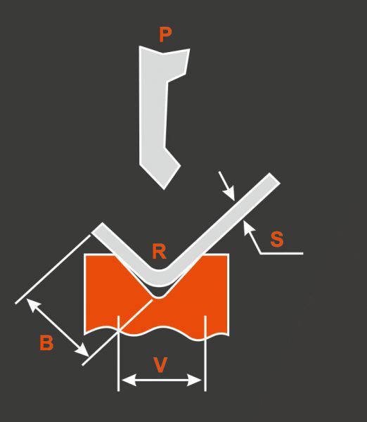
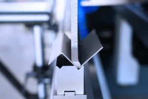
Before using the Hydraulic Press Brake to bend the material, it is necessary to adjust its various data, including the bending force, the backgauge distance, the upper limit of the slider, the slider speed, and the adjustment of the upper and lower die clearances, so that it can reach Actual operation requirements. How to adjust these parameters?

Regarding the adjustment of the Hydraulic Press Brake, the kN value of the sheet bending force is mainly calculated according to the calculation formula, and the indicated pressure P value is calculated according to Table 1. Then the handwheel of the relief valve is adjusted to make the force slightly greater than Thousand Newtons of Folding Plate.
The adjustment of the distance of the rear stopper of the Hydraulic Press Brake requires positioning in the length direction when the sheet is bent. The motor is adjusted by the buttons on the front button box. The adjustment value can be read from the number of revolutions table on the button box. The conversion value of the revolution table is 0.1mm / revolution, and there is a handwheel for fine adjustment.
Hydraulic Press Brake The upper limit of the slider needs to be adjusted by adjusting the position of the bumper block Ⅱ. The rising slider can stay at the desired top dead center position, which can shorten the stroke distance of the slider and reduce the working cycle time, thereby improving productivity. The adjustment of the slow motion of the slider is related to the collision block I. When the stroke switch is triggered, the slider performs a slow motion, and the length of the slow stroke time is adjusted by an adjustable potentiometer.
The adjustment of the clearance between the upper and lower molds in the Hydraulic Press Brake is completed by operating the buttons on the button box at the lower right of the worktable. The direction of operation is indicated by the bending machine label. Size to trim the gap. Of course, you can also use the handwheel to make fine adjustments. The adjustment value is displayed by the calculator. Each single digit is 0.1mm. If the two ends of the workpiece angle are inconsistent, loosen the nail, move the connecting rod to the left, disconnect the left and right rotation connections, and turn the handwheel to change the mechanical limit distance at one end to achieve the purpose of finely adjusting the angle of the workpiece end.
Learn more about our products, please visit and subscribe to our Youtube channel


