The plate rolling machine, also referred to as a plate bending machine or plate roller, is a type of sheet metal forming equipment that uses rollers to bend and shape metal sheets. This machine is capable of producing various shapes, including cylindrical and conical components. It plays a crucial role in sheet metal bending and forming processes.
Definition of Plate Rolling Machine
A plate rolling machine is designed to shape various metal sheets into rounded or conical forms. Its serve as the perfect tool for pre-bending and rolling metal sheets.
The plate bending machines are essential for fabricating rounded components used in oil and gas rigs, tunnel supports, boiler equipment, pressure vessels, heat exchangers, and more.
At the forefront of innovation, BIT specialize in 3-roll or 4-roll bending machines for plate rolling, actively advancing technology to meet future demands and exceeding the expectations of industry-leading clients. The plate rolling machines drive production across diverse sectors, including construction, transportation & logistics, energy production, machinery manufacturing, and beyond.
In China, BIT’re reputed and continously prove to develop and produce the market’s strongest Plate roller (Plate Rolling Machines).
Plate rolling machines can be divided into two-roller, three-roller, and four-roller. The three-roll plate rolling machine can be divided into two types: symmetrical and asymmetrical.
2-roll plate rolling machine
The 2-roll plate rolling machine is a type of equipment that boasts two rollers, an upper rigid metal roller, and the lower elastic roller. The sheet material is passed in between the rollers, and when force is applied, the metal adheres to the power assuming a cylindrical shape. Used on thin metals for high production operations (filters, canisters, etc.)
The 2-roll plate rolling machine is configured with polyurethane roll which, by exerting dynamic pressure, speeds up the plate forming process, assuring the straight end of the produced rolls is removed and greatly simplifying the prebending-rolling-prebending sequences typical of 3-roll or 4-roll steel plate rolling machines.
3-roll and 4-roll plate rolling machine
The working principle of the plate rolling machine is the same as that of the profile bending machine according to the principle of three points forming a circle, the relative position change and rotational motion of the workpiece are used to produce continuous plastic deformation of the plate to obtain a workpiece with a predetermined shape. According to the rotational movement and position changes of work rolls of different shapes, elliptical parts, arc parts, cylindrical parts, and other parts can be processed.
Static pre-bending and Dynamic bending
Static pre-bending and dynamic bending are two distinct methods used in plate bending processes.
Static pre-bending involves holding the metal sheet stationary while a roll ascends along the sheet, bending the leading edge. This method is characterized by the sheet being held in place during the bending operation.
In contrast, dynamic bending entails the plate or sheet being in motion as it runs through the bending machine. The continuous motion of the sheet facilitates a more efficient operation of the machine, leading to increased bending thickness capability.
Dynamic bending offers advantages in efficiency and productivity, as the continuous motion of the sheet allows for faster processing and potentially thicker materials to be bent compared to static pre-bending.
Both methods have their respective applications and are chosen based on factors such as material type, thickness, and desired bend characteristics. Dynamic bending is often preferred in high-volume production environments where speed and efficiency are crucial, while static pre-bending may be suitable for precision bending applications requiring careful control over the bending process.
Working Principle of Symmetrical 3-roll Plate Rolling Machine
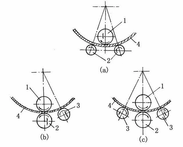
The picture above (a) is a cross-sectional view of the rollers of a symmetrical 3-roll bending machine. The rollers have a certain length in the axial direction so that the entire width of the sheet is bent.
There is an upper roller 1 at a symmetrical position in the middle of the two lower rollers. The upper roller can be adjusted in the vertical direction so that the sheet material 4 placed between the upper and lower rollers can obtain different bending radii. The lower roller 2 is active and is installed in a fixed bearing. The motor rotates in the same direction and at the same speed through a gear reducer. The upper roller is passive and installed in a bearing that can move up and down. The adjustment of the rollers on the large plate rolling machine is mechanical or hydraulic, and manual adjustment is often used in the small plate rolling machine.
When working, the sheet material is placed between the upper and lower rollers, and the upper roller is pressed down to make the sheet material bend between the support points. When the two lower rollers rotate, the sheet material moves due to the action of friction, so that the entire sheet material is evenly bent.
According to the above bending principle, the required bending radius can only be achieved when the part of the sheet material is in contact with the upper roller, so the edges of both ends of the sheet have a length that does not contact the upper roller and does not bend, which is called The remaining straight side, the length of the remaining straight side is about half of the distance between the two lower rollers.
Variable-geometry 3 Roll Bending Machines
Variable-geometry 3-roll bending machines offer unparalleled versatility, allowing for the widest range of material types and thicknesses relative to the size of the top roll. These machines excel in medium and thick plate bending applications.
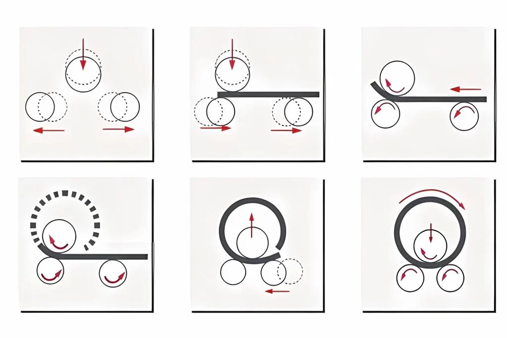
The operational principle of the three-roll variable pitch involves all three rolls being capable of movement and tilt. While the top roll operates in the vertical plane, the side rolls move horizontally. During the rolling process, the top roll applies pressure to the metal plate between the two side rolls. The variability of the three-roll design enables the rolling of various thicknesses and diameters of cylinders. Such machines feature one pressing top roll and two pressing side rolls.
The horizontal movement of the side rolls ensures the plate remains in a horizontal position, facilitating quick and efficient pre-bending execution. The configuration of the three rolls, with the top roll moving along the vertical axis and the two lower rolls moving along the horizontal axis, allows for independent adjustment of the center distance of the top bending roll with each lower roll. Consequently, by reducing the distance between the lower rolls and applying pressure with the top roll on the initial part of the plate, the straight portion can be minimized, achieving perfect pre-bending.
Expanding the center distance of the lower rolls significantly enhances the rolling capacity. In the 3-roll variable geometry plate bending machine, the top roll is motorized, while the two lower rolls are free, equipped with an automatic braking system ensuring high reliability. Additionally, the machine can be outfitted with three driving rolls for bending thinner plates. Roll parallelism is meticulously controlled and managed by a PLC, guaranteeing maximum precision in roll positioning with minimal tolerances.
For instance, the side rolls play a crucial role in generating mechanical advantage. Adjusting the side rolls allows for varying degrees of mechanical advantage. When the side rolls are fully open, the machine achieves maximum mechanical advantage, while closing them reduces this advantage. Thus, a machine capable of rolling 2-inch-thick material with maximum mechanical advantage can handle jobs as thin as 1/2 inch by reducing the mechanical advantage accordingly. Furthermore, the independent axis of each roll contributes to achieving a perfect bend. The back-side roll, situated at the far side of the feeding point, serves as a back-gauge, ensuring proper plate alignment and eliminating the need for operator assistance.
Double-pinch 3 Roll Bending Machine
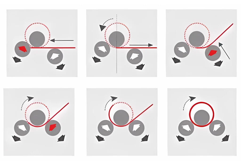
Double-pinch 3 roll bending machines are available in a range of capacities, from light to very heavy, offering significant advantages over three-roll initial-pinch machines. Unlike initial-pinch 3-roll bending machines, they eliminate the need for operators to remove, flip, and then attempt to square the plate a second time after pre-bending. This is because cylinders can be rolled to the required diameter immediately after pre-bending, as the material can be kept within the machine—a feature not possible in initial-pinch 3-roll bending machines.
In a plate bending machine, the side rolls are positioned to the right and left of the top roll and share the same axis, contributing to the bending process. Additionally, the back-side roll serves as a back-gauge to square the plate for proper alignment, eliminating the need for manual assistance.
For cone rolling on a double-pinch 3 roll bending machine, the side rolls can be tilted to establish the desired cone angle, providing versatility in shaping.
When pre-bending on a 3 roll plate rolling machine, plates are tilted down as they are fed. In contrast, on a four-roll machine, plates are loaded horizontally at the feed level, allowing the use of horizontal motorized roller tables to aid in feeding the plate.
Working principle of asymmetric 3-roll plate rolling machine
Figure 7-1(b) is the bending drum diagram of the asymmetric three-roll plate bending machine. The upper roll 1 is located on the top of the lower roll 2, and the other roll 3 is on the side, which is called the side roll. The upper and lower rollers are rotated by the same motor. The lower roller can be adjusted up and down, and the maximum distance of adjustment is approximately equal to the maximum thickness of the steel plate that can be bent. The side roller 3 is passive and can be adjusted in the inclined direction.
When bending, sheet material 4 is fed into the upper and lower rollers, and then the lower roller is adjusted to compress the sheet material to generate a certain frictional force, and then the position of the side rollers is adjusted. When the upper and lower rollers are driven by the motor to rotate, the sheet material is bent.
The advantage of this asymmetric three-roll plate bending machine is that the edges at both ends of the plate can also be bent, and the length of the remaining straight edge is much smaller than that of the symmetrical three-roll plate bending machine, and its value is less than twice the plate thickness. Although the sheet material cannot be bent between the side roll and the lower roll, the whole bending process can be completed as long as the sheet material is taken out from the rolling machine and then turned around and bent.
Single-pinch 3 Roll Bending Machine
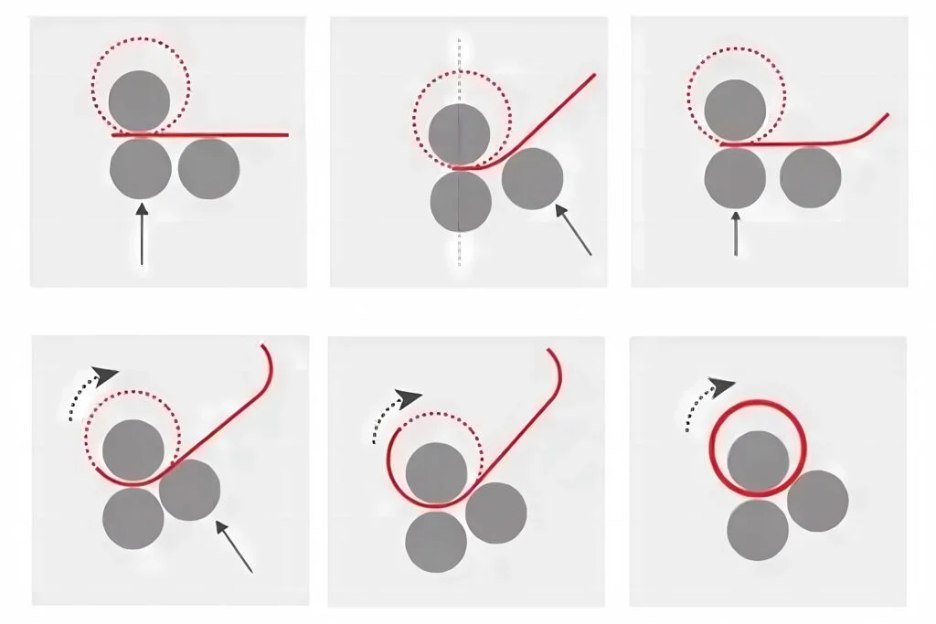
Single-pinch 3-roll bending machines/asymmetric 3-roll plate rolling machine typically necessitate inserting the sheet metal twice to pre-bend both ends. However, there are also double-pinch models available, streamlining the pre-bending process on both ends, enhancing efficiency, speed, and precision.
Single initial-pinch 3-roll plate rolling machines are generally best suited for light-capacity applications. They may operate electromechanically or hydraulically, pinching the flat sheet between two vertically opposed rolls while the third bending roll moves upward to contact and bend the sheet. These machines, often older in design, typically require the removal and reinsertion of the sheet to pre-bend both ends. While cost-effective, they tend to be more labor-intensive in a production setting compared to their modern counterparts.
The working principle of the 4-roll plate rolling machine
Figure (c) is a four-roll plate rolling machine, which is basically similar to the asymmetric three-roll plate rolling machine, except that one side roller 3 is added. It eliminates the trouble of turning around and bending the sheet on the asymmetric three-roll rolling machine.
4 Roll Bending Machines feature a top roll, a pinching roll, and two side rolls, enabling them to produce bends with unparalleled speed and accuracy. These plate rolling machines are renowned for their efficiency.
The flat metal plate is positioned within the machine, typically on one side, and undergoes pre-bending on the same side. The side rolls execute the bending action while the pinching roll securely holds the plate in place. With the plate firmly clamped between the top and bottom rolls, the side rolls move vertically to initiate the bend. As the bottom roll ascends to maintain secure contact with the top roll, the side roll is raised to achieve precise pre-bending, minimizing any flat zones on the plate’s edge.
Plate feeding can occur from either side of a 4-Roller Plate Rolling Machine. When fed from a single side, these machines can be placed against a wall, optimizing floor space utilization.
The side rolls are positioned to the right and left of the bottom roll, each operating on its own axis. This independent axis configuration contributes to achieving flawless bends. Additionally, the back-side roll, located opposite the feeding point, serves as a back-gauge, ensuring plate alignment without requiring operator assistance.
The constant secure clamping of the top and bottom rolls maintains plate squareness without slippage during both pre-bending and rolling processes. Unlike three-roll initial-pinch machines, 4-Roller Bending Machines eliminate the need for operators to remove, flip, and square the plate a second time after pre-bending, enabling a more streamlined operation. Additionally, a cylinder can be rolled to the desired diameter immediately after pre-bending, as the material remains within the machine.
Bending of the back edge occurs post-cylinder rolling, allowing for a one-direction, single-pass operation. For cone-rolling applications, the side rolls can be tilted to establish the cone angle, while the bottom roll can also be tilted to clamp and drive the major end of the cone.
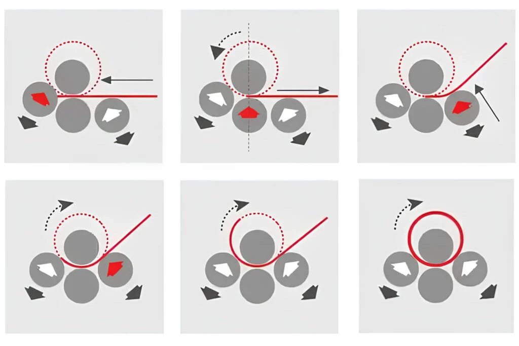
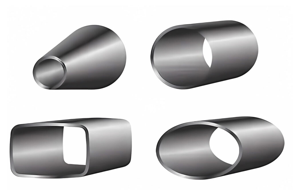
4-Roller Plate Benders offer versatility, enabling the creation of rectangular, elliptical, and square-shaped outputs by precisely bending the metal in specific areas as it passes through the machine.
Cone bending
Cone bending is a specialized application of plate rolling, where a metal plate is shaped into a cone structure. To achieve this, the metal plate must be accurately cut to the correct dimensions before bending. Typically, a flat metal blank with the appropriate inner and outer radius is prepared to form the desired cone shape.
During the bending process, the blank is fed into the plate roller with one side aligned against a cone rolling attachment. The inner radius of the blank is fed through the roller at a slower rate compared to the outer radius. This meticulous process demands precision and exactness, resulting in the time-consuming fabrication of cones.
Both three-roll and four-roll plate rolling machines can be employed for cone bending. These machines have the capability to incline the forming rolls in a positive attitude, and they should be equipped with a hardened contrast die to regulate and slow down the speed of the smaller diameter.
Guiding the small diameter and inclining the rolls are essential steps in successfully rolling a cone. This process creates an atypical scenario for the rolling operation. However, on a three-roll double pinch machine where all three rolls are driven, it becomes challenging for the contrast die to effectively retard the rotation of the small diameter while simultaneously moving the larger diameter at a faster rate.
In contrast, a four-roll machine equipped with inclinable forming rolls and a hardened contrast die is better suited for rolling cones. The additional control provided by the inclinable rolls and the contrast die enhances the precision and efficiency of the cone bending process, resulting in superior cone fabrication compared to a three-roll machine.
Radius of curvature
The plate rolling machine typically consists of three parallel steel rollers arranged in a triangular formation. As the sheet metal passes between the upper and lower rollers, it undergoes a transformation, developing a curvature known as the radius of curvature. This radius depends on the relative positions of the three rollers.
In plate rolling, the radius of curvature refers to the curve formed when a metal sheet is bent into a cylindrical or conical shape. It represents the distance from the curve’s center to the outer edge of the rolled plate. The radius is influenced by factors such as plate thickness, width, roller diameter, and the bending process used. A smaller radius results in a sharper bend, while a larger radius creates a gentler curve.
Achieving the desired radius requires precise control over the bending process, including adjusting roll positions, pressure, and feed rates. Modern rolling machines often feature adjustable geometry or roll positions to accommodate a variety of radii for different needs.
Deformation Analysis of the Bending Process
According to the characteristics of rolling deformation, the plate rolling process can be divided into elastic deformation, elastic-plastic deformation, and pure plastic deformation stages.
In the initial stage of the bending of the barrel blank, the external bending moment is not large, the value of the internal stress is less than the yield limit σs of the material, and only elastic deformation is caused inside the blank, which is called the elastic deformation stage. When the value of the external bending moment continues to increase, the internal stress exceeds the yield limit, and the deformation in the deformation zone of the blank transitions from elastic deformation to elastic-plastic deformation and pure plastic deformation.
Deformation Analysis
As can be seen from the above figure, the upper stress of the blank section transitions from the outer tensile stress to the inner lamination stress, and there must be a layer of metal in the middle, whose tangential stress is zero, called the stress neutral layer, and its curvature radius is represented by ρσ. Similarly, the distribution of strain transitions from the tensile strain of the outer layer to the compressive strain of the inner layer, and there must be a layer of metal with zero strain in between, that is, when the coil is deformed, its thickness remains unchanged, which is called the strain neutral layer, and its radius of curvature It is represented by ρε. This is the basis for accurately calculating the unrolled size of the round blank. When the deformation is small, ρσ=ρε=r+t/2, that is, the stress neutral layer and the strain neutral layer overlap, and in the middle of the blank thickness, when the deformation is large, the stress neutral layer and the strain neutral layer are opposite to each other. Inward displacement and the displacement of the stress neutral layer is greater than the displacement of the strain neutral layer, that is, ρε>ρσ, in the production of coiled plates, the following empirical formula can be used to determine the position of the strain neutral layer, namely
ρε=r+xt (7-1)
In the formula: ρε——curvature radius of strain neutral layer, mm; r——involution circle radius, mm; x——coefficient related to the degree of deformation, take x=0.33; t——material thickness, mm.


