Running into problems with press brake deformation management while forming parts on a press brake? Don’t worry! You can boost throughput by applying creative strategies to handle feature-deformation bending issues. This guide explores the causes of part deformation and how to prevent problems before they start. By spotting potential issues early on, you’ll find more reliable solutions for effective press brake deformation management.
The Bend-Line Danger Zone
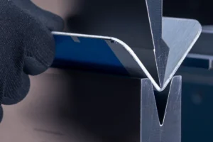
A common headache for press brake operators is when a feature too close to the bend line gets deformed. This could be a hole, a window, or even the part edge. A feature near the die space can have a negative impact on the bend. Picture a piece of sheet metal folding – the bend line will naturally flow towards the area with the least resistance, just like water flowing downhill.
Normally, a form’s material edge stands perpendicular to the bend line. But when this angle changes, it’s like pulling on a rubber band, stretching the dimension and causing a pucker on the outside of the bend. This is called a “blowout,” which is the part of the material that resists forming because it lacks support during the process. Depending on how bad the blowout is and how much surrounding material is there to support it, this could also make the tooling bend or shift, like a wobbly bridge under too much weight.
Handling Holes
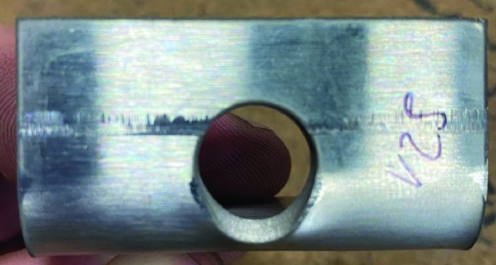
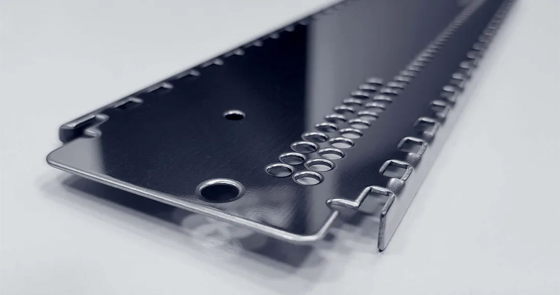
When a designer makes a sheet metal part meant to be attached to something, it will surely have holes. These could be tapped holes for bolts or just plug-weld holes. In Fig. 1, a 12-gauge stainless steel piece with a ½-inch diameter hole, placed ⅛ inch from the bend line, was bent in a 0.984-inch-thick, 88-degree V die. The result? The hole got really deformed. Some hole deformation might be okay, depending on what the part is used for, but when it’s not, the fabricator has to find a fix.
Pilot
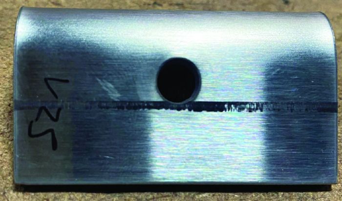
One solution could be “piloting.” It’s like making a rough draft first. You reduce the hole size during blanking and then drill it to the right size after forming. In Fig. 2, the hole diameter was shrunk to ¼ inch, using the same V die as in Fig. 1. This cuts down on the hole’s interference in the die space. If there’s a little deformation, it will probably go away when you drill the hole to the final size. But remember, this adds an extra step downstream, and some holes might be impossible to reach after forming. It’s just one option in the toolbox.
Bend-line Slit

Another possible fix is the “bend-line slitting,” which is like cutting a small notch on the bend line. The idea is to intentionally create a weak point where the material should form on the bend line instead of the feature. This stops the bend line from being pulled and gets rid of the pucker. Fig. 3 shows a slit that’s longer than needed. The slit width only has to be as wide as the feature. Again, this was bent in a 0.984-inch-thick, 88-degree V die. But slits might not be allowed in the final part, so you might have to weld and clean the area, adding more steps downstream.
Another Bend-line Slit Alternative
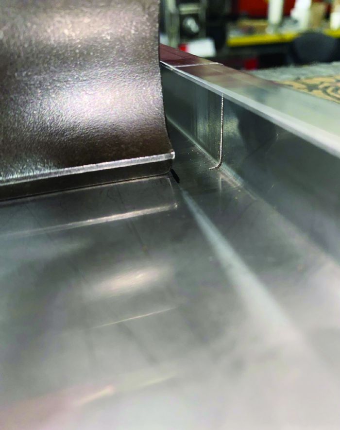
Another good alternative for a bend-line slit is when the tooling stops before the material edge. Often, return flanges can mess with the tooling. Horn punches, or ear tools, are cut away to reach some of these shapes (Fig. 4). But what if you don’t have them or they don’t match the tooling geometry? Just slit the bend line from the material edge to the end of the tool. This also works for lower-die gaps when the return flanges go down.
Downsized V Opening
These are great ideas, but what if blanking has already happened? One choice could be a smaller-than-standard V opening. Recommended V openings are usually for getting the best and most consistent results. But going down a size or two might reduce the feature interference enough to avoid costly rework. Smaller V openings will increase spring back, tool-marking, and tonnage requirements, though. Always double-check the bend’s tonnage needs and the tool’s and machine’s limits to avoid overloading, like making sure you don’t put too many things in a small box that can’t handle the weight.
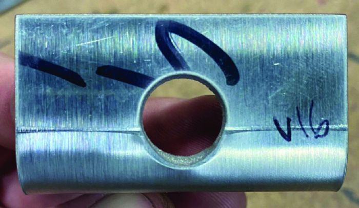
The example in Fig. 5 shows a 0.630-inch-thick, 88-degree V die, which cut down on the deformation but didn’t get rid of it completely. Tooling geometry also affects the amount of blowout. A die with a larger shoulder radius or an acute die will let the material slip earlier in the forming process, making any potential blowout worse, like a slippery slope that makes things slide out of control.
Support the Sheet
If a downsized die opening doesn’t work, supporting the sheet during the bending process might be the only way to go. A rotary cam die has rotating semicircular inserts that let the material slide across the working surface while keeping pressure on the blank. It’s like having a helping hand that keeps the sheet in place. This constant contact with a hard surface usually stops deformation, but the operator should still keep a minimum distance from the bend line to the feature. And no extra processing is needed after that.
Use Sacrificial Backer
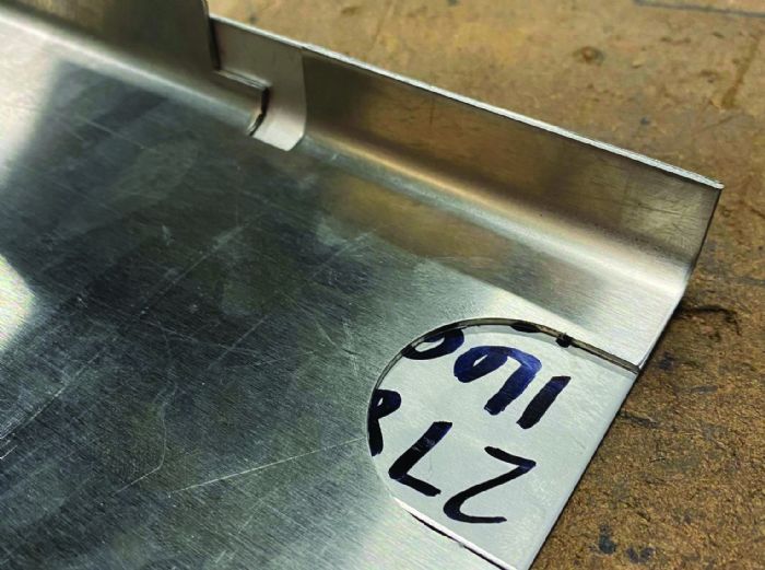
No rotary cam dies available? The operator can try using scrap material as a “sacrificial backer.” It’s like having a backup dancer that gives support. You place a blank under the workpiece to add support during the bending cycle (Fig. 6). The backer has to be as strong as or stronger than the workpiece, or it will tear, and the workpiece will deform. Using a different material or thickness might cause different amounts of spring back between the workpiece and the backer. Ideally, use a backer that’s the same length, thickness, grade, and temper as the work material. You might need a larger-than-normal V opening to account for the increased thickness of the part and the backer. In the example, a 16-gauge stainless-steel part with a short flange wouldn’t bend properly without support from a backer. The backer is the same material as the workpiece. The punch nose radius is 0.236 inches, and the 88-degree V die is 0.787 inches thick.
Windows, Miters, and Radii
Windows, or cutouts, deform in a similar way to holes when the window edge is in the die space and not perpendicular to the bend line. Often, a window edge is parallel to the bend line. This will pull the dimension a lot, like stretching a piece of taffy, as it blows out. The window length is another thing to think about when figuring out if deformation will happen. Longer windows will have more deformation because more material will fall into the die space.
Miters pull the bend line towards the area with the least resistance, like a magnet attracting metal. This is the side with the least amount of material in the die space. When you can, at the start of the forming process, force the bend to pull towards the stops and keep pressure on them, instead of away.
The solutions for managing distortions in windows are a lot like those for holes, with a few differences. Rotary cam dies and sacrificial backers help support the bend and reduce the pulling effect. Bend-line slitting creates a fold point by making a weak spot. Piloting isn’t a great option here because a noncircular shape usually can’t be added easily downstream, unless the part will be machined on a mill or with EDM later. But this does offer another similar pre-blanking solution.
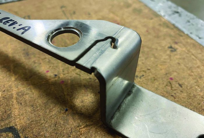
Sitting, Silhouetting, Tabbing. These are all ways of intentionally not cutting feature lines during blanking to keep the skeleton attached to the workpiece for extra support during forming (Fig. 7). Lines that are perpendicular can be cut without worrying about deformation. Lines parallel to the bend line are left uncut. Depending on how much deformation is okay, miters and radii may be cut.
Removing the tabbed skeleton needs some space designed inside a window feature to allow for the cutting operation after forming. The example shows a unique feature that wouldn’t work without using an unlit.
Don’t like the idea of adding a downstream process just for miters? There are two good things about this. Often, miters reduce the distance between the back gauge fingers to a small fraction of the overall bend length. Tabbing a square skeleton to the mitered edge can increase this distance, making the back gauge more correct, like adjusting the sights on a gun to shoot more precisely.
Smallest Flange
Often, rotary cam dies can manage short flanges. Check with the tooling supplier for the smallest flange size the tool can bend without catching the flange. Forming a flange shorter than this minimum can make the edge slip inside the rotating inserts and damage the tool. A common range of around 60 to 70% of the die width is recommended, like knowing the right size shoe to fit your foot without it being too loose or too tight.
While a sacrificial backer probably won’t make a short flange bend on its own, it can help support parts of a short flange during a bend. Unlike a hard-surfaced rotary cam die, a backer bends (and deforms) along with the workpiece. The stiffer the backer, the less it will deform and the more likely the workpiece will keep its shape, like a strong foundation that holds up a building.
Machined Surfaces
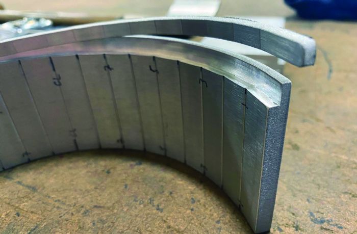
Press brake operators can stop deformation on a machined surface by using a sacrificial blank to fill the space (Fig. 8). If there’s a machined surface on top of the part, the blank will act like a punch wrapper, making the pushing radius equal to the punch nose plus the blank’s material thickness. If the machined surface is on the bottom, the blank will act more like a sacrificial backer and support the forming process, as long as it covers the die gap. For step-bending, a set of C clamps might seem like a good idea, but the bends of the workpiece and the sacrificial blank might stretch at different rates. Double-sided tape can help keep the blank and workpiece together while allowing a little bit of movement to cover any differences, like a flexible joint that holds two parts together but still lets them move a bit.
Finding Balance for Press Brake Deformation Management
These methods often come with extra processes that add to the cost of the final part. Designers and fabricators need to collaborate effectively to create useful parts at a reasonable price. Designers should avoid placing features near bend lines whenever possible to simplify press brake deformation management. If a close feature is necessary, a fabricator can apply one of these strategies to salvage a part that would otherwise be ruined. This list isn’t exhaustive—if you encounter similar challenges, you may develop your own solutions for effective press brake deformation management.
