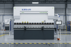
It is your first day on the job, and you are training to become a press brake operator at KRRASS. You notice press brake tooling artfully arranged on carts beside each machine. Some operators use a single tool set, while others set up multiple tool sets across the machine.
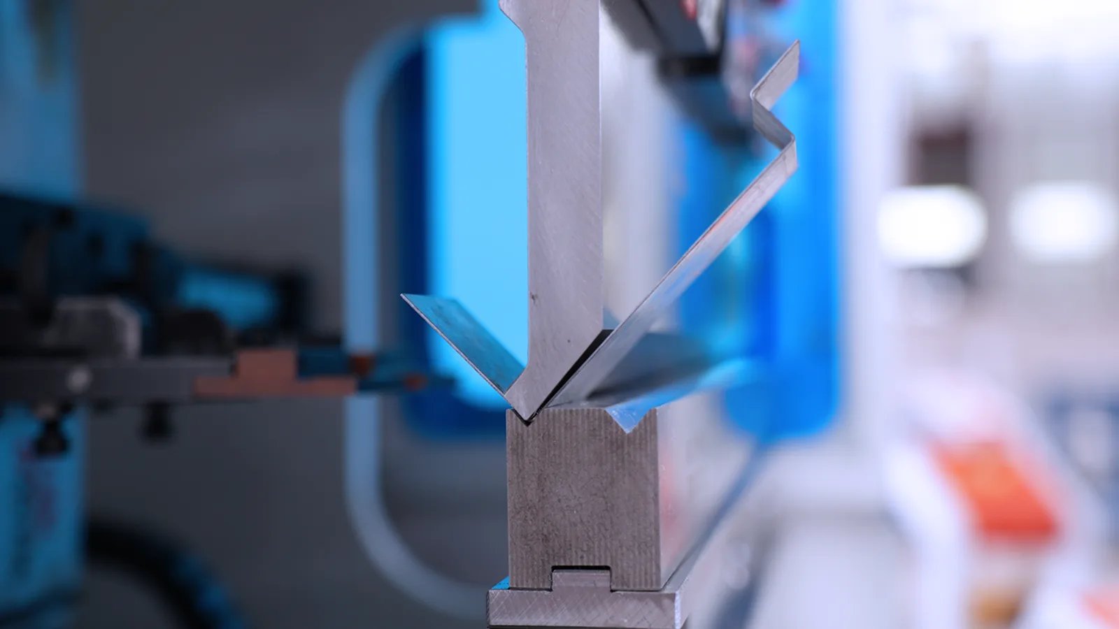
The operation looks straightforward: An operator slides a sheet metal or plate piece between two tools. The upper tool (the punch) moves downward toward the lower tool (the die), bending the metal. Simple enough, right?
Not exactly. The bending process is one of the most complex tasks in metal fabrication. Everything depends on how the punch and die interact with the metal.
Basics for Curious Beginners
For years, many new employees have no prior experience. Some companies even need to train newcomers to read tape measures.
There are two types of new operators. One type just wants a paycheck and is not interested in deeper learning. This guide is not for them. The other type is curious and eager to advance, becoming a team leader or a skilled technician. This guide is tailored specifically for these curious beginners, starting from the absolute basics, like understanding what "bend radius" means.
Understanding the Radius Basics
Sometimes engineers receive CAD models from customers that show sheet metal bends without a radius. Though modern software helps prevent this, it is a reminder of how misunderstood metal bending can be—even among manufacturers. Let us clarify:
Every bend has an angle and a radius. The angle is straightforward, though it is important to understand whether the drawing shows an internal or external angle (Figure 1).

But what is a radius? In metal bending, a radius describes the curve formed in sheet metal or plate. Remember geometry class? Imagine a circle—draw a straight line from the center of the circle to the edge. That is your radius. The smaller the radius, the sharper the bend.
Drawings often specify the radius as "R.120" or something similar, pointing to the bend's inner side. This means the inside bend radius should measure 0.120 inches. Visualize a circle matching the curve's edge; that is your bend radius (Figure 2).

What Happens During Bending
When metal bends on a press brake, it stretches slightly. This happens because the metal experiences compression on the inside and stretching on the outside of the bend (Figure 3). This stretching and compression move the metal’s neutral axis inward. Professionals call this the "k-factor." Because of this, metal dimensions slightly grow.

Operators and software use the k-factor to calculate bend allowance (the length along the neutral axis) and bend deduction (the dimension subtracted from the original length). Knowing this helps create accurate bends.
Punches and Dies
When operators insert metal blanks (laser-cut or punched sheet metal pieces) between punches and dies, the metal must touch back gauges or stops for accurate bending.
The shapes of punches and dies significantly influence bending. A punch typically has a punch tip radius and a punch angle. The die has a "V" shape, with a specific die angle and a rounded edge called the die shoulder radius (Figure 4).

The punch angle must not exceed the die angle, or tool damage and accidents could occur (Figure 5). For larger bends, you might use round punches, which effectively have a 90-degree punch angle (Figure 6).


Methods of Bending
The bending process starts the same way regardless of method: the punch presses the sheet metal into the die. But from this point, methods vary:

- Bottoming: The punch presses metal fully into the die, shaping it precisely. Punch radius determines the inside bend radius, and die angle sets the bend angle (Figure 7).
- Air Bending (Air Forming): Most modern factories, including KRRASS, prefer air bending. Here, the die opening determines the inside radius, not the punch tip. Wider dies create larger radii and need less force. Narrow dies increase bending force, which can risk tool and machine damage (Figure 8).

In air bending, punch and die angles do not directly affect the final bend angle. The depth the punch pushes into the die determines the angle.
Die width also determines the smallest flange (the narrowest bend edge) achievable. Parts must stay securely on die shoulders during bending. Narrower die angles help manage spring back, where metal slightly reverts after bending.
Tool Selection: Planed vs. Precision-ground.
Operators might use two tool types, depending on the accuracy needed:

- Planed tools: Used for general bending tasks. Operators usually measure these parts using tape measures. These tools are long and might be cut into shorter lengths. Proper labeling is crucial for reassembly accuracy (Figure 9).
- Precision-ground tools: For exact, precise bends. Operators measure these with digital calipers and radius gauges. These tools are segmented and made to tight tolerances.
Tooling Types Explained
Common tool types include American, European-style, and New Standard tools, each with different mounting styles and bending force flow. New operators should know the types of their facility uses and how to mount them correctly (Figure 10).

Sometimes you need to reverse punches for complex bend sequences to avoid collisions. Punch types, like gooseneck punches, allow bending without hitting previously bent parts (Figure 11). Some punches have windows cut out for clearance.

Dies also come in various forms. Double-V and four-way dies offer multiple die openings in a single tool, suitable for different bends (Figure 12). Specialized non-standard tools, like urethane pads within relieved dies, protect workpieces and improve bending accuracy (Figure 13).


Stage Bending and Machine Setups
Sometimes operators set multiple tools across the brake, performing several bends on one machine, called "stage bending." Every punch and die set must have an identical shut height—the distance between machine ram and bed at the bottom stroke. Operators may use shims or risers to align dies correctly (Figure 14).

Modern software, helps program back gauges for complex bending sequences. This automated back gauge movement is far more accurate than manual adjustments once required by older machines.
The Physics Remain the Same
New operators will see both old and advanced press brakes. Newer machines offer 3D visualizations and automated tool placements, simplifying the process. Yet, the underlying physics of bending never change. Understanding these fundamentals creates a solid foundation for any future skilled press brake operator.