In the realm of sheet metal fabrication, choosing the right tools for press brakes can be a daunting task for many businesses. Understanding how to select the appropriate tooling setups tailored to specific bending requirements is crucial for achieving precise and flawless results. If the tool is not suitable for the material or thickness, it may result in incomplete bends, cracks, deformations or other surface defects. However, Press brake tooling chart serves as a guide for selecting the appropriate tooling setups based on the specific requirements of the bending operation. Different materials, thicknesses, and bending angles may necessitate different tooling configurations, and the article helps operators make right decisions…
Introduction
What is Press Brake?
A press brake is a machine tool commonly used in sheet metal fabrication to bend and form sheet metal into various shapes. It works by applying force to a workpiece through a punch and die set, which results in bending the material at a specific angle. Press brakes come in different sizes and configurations, ranging from manual and semi-automatic models to fully automated CNC (Computer Numerical Control) machines.
Relationship Between Press Brake and Press Brake Tooling
Dependence: Press brake tooling is an integral part of the press brake operation. Without suitable tooling, a press brake cannot perform bending tasks effectively.
Functionality: Press brake tooling determines the types of bends and shapes that can be achieved. Different tooling configurations are used for various bending operations, such as air bending, coining, and bottoming.
Compatibility: Press brake tooling must be compatible with the specific press brake machine being used. The size, tonnage capacity, and tooling mounting system of the press brake must match the requirements of the tooling.
Accuracy: The precision and quality of the bending process depend on the accuracy and condition of the press brake tooling. Properly maintained and aligned tooling ensures consistent and accurate bends.
Flexibility: The availability of a diverse range of press brake tooling allows for versatility in sheet metal fabrication. Operators can choose the appropriate tooling based on factors such as material type, thickness, bend angle, and desired end product.
Efficiency: Well-designed press brake tooling, combined with a properly set up press brake machine, contributes to increased efficiency and productivity in sheet metal bending operations. It minimizes setup time, reduces scrap, and enhances overall workflow.
Press brake tooling and press brake machines work in tandem to achieve precise and efficient bending of sheet metal components. The selection, compatibility, and proper maintenance of press brake tooling are crucial aspects of optimizing the performance of a press brake system.
Understanding Press Brake Tooling
What is Press Brake Tooling
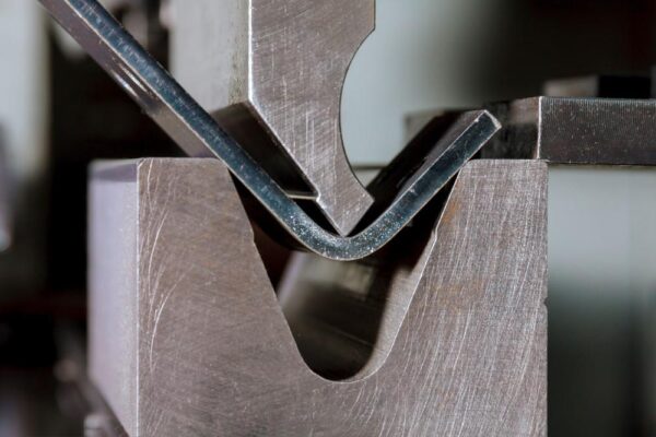
Press brake tooling is the equipment like dies and punches used in the press brake to create the bend in a sheet metal. Press brake tooling is not built into the machine. It is rather a swappable part of the machine that is used based on the particular type of job. Press brake tooling is the accessory that actually comes in contact with the workpiece.
Common press brake toolings
- Punch and Die: Punch and die sets consist of an upper punch and a lower die, used to apply pressure on the workpiece to create the desired bending angle.
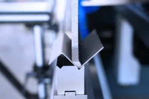
- V-Die: V-dies are shaped like a V and used in conjunction with a punch to create V-shaped bends in the workpiece.
- U-Die: U-dies are shaped like a U and used with a punch to create U-shaped bends, commonly used for forming box-shaped or channel-shaped components.
- Bottom Tooling: Bottom tooling provides support to the workpiece during bending and is typically made of hardened material to withstand pressure and maintain the shape of the workpiece.
- Angle Tooling: Angle tooling is used to create bends at specific angles, such as 90-degree angles, commonly used in the fabrication of angle iron and similar components.
- Multistep Bending Tooling: These toolings allow for multiple bends to be made in a single step, reducing the number of operations required and increasing production efficiency.
- Custom Tooling: Custom tooling is designed and manufactured for specific workpiece requirements, allowing for the production of non-traditional shapes and bends.
These are some of the common press brake toolings used in sheet metal fabrication. Each type of tooling serves a specific purpose and can be selected based on the shape, size, and requirements of the workpiece.
Variations in Bending Under Press Brake Punch and Die
Air bending:
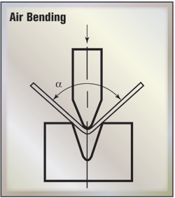
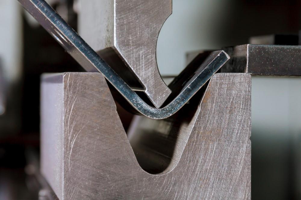
With air bending, the punch presses the workpiece into the die without pressing it against the walls. While the punch moves down, the sides of the workpiece bend up, which creates the angle. The deeper the punch presses the workpiece into the die, the more acute the angle. A clearance remains between the punch and the die. Air bending is referred to as a path-dependent method, as each angle requires a defined path. The machine control calculates this path as well as the appropriate press force. The path and press force depend on the tools as well as the material and product properties (angle, length).
Bottoming:
In bottom bending, the punch presses the workpiece into the die completely so that there is no clearance between the die, workpiece, and punch. This is called a form lock. The punch and die must fit into each other exactly. For this reason, a separate tool set is required for each angle and each form. When the workpiece has been completely pressed in, the punch cannot move further down. However, the machine control increases the press force until the predefined value has been reached. This increases the pressure on the workpiece, which then takes on the shape of the punch and the die. The angle stabilizes under the high pressure so that springback is almost completely eliminated.
Folding and hemming:
Sheet edges are often bent over completely, such as the edges of boxes. The sides are then parallel to each other. This either makes the finished part more stable or creates edge protection. Furthermore, folds are often needed so that another part can be hooked into them at a later stage. Folding and hemming occurs in two steps. In the first step, the operator pre-bends an angle of 30°. Then they reinsert the workpiece and press the angle shut. The procedure is called folding if a gap remains between the sides. With hemming, the sides are pressed completely together. Folding is path-dependent, but hemming is force-dependent.
Panel bending:
The bending frame in the machines is comprised of a C profile onto which the lower and upper bending tool are mounted. When the sheet metal is bent, the C profile moves up or down and performs a small elliptical movement (the swivel). Panel benders are semi-automatic and are characterized by their speed and flexibility, in particular when handling small quantities. Panel bending can also be used to productively bend different radii sizes on a component using the same tool.
4 Press Brake Tooling Styles
American Precision Style:
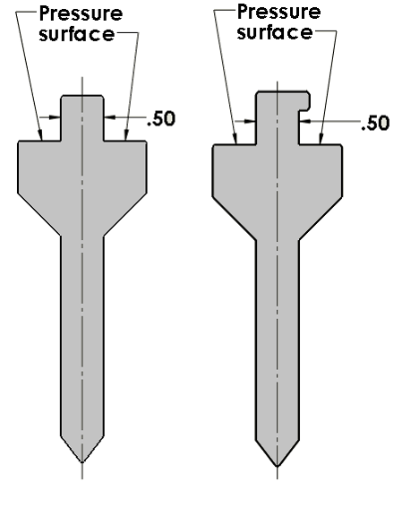
American Precision Style tooling features a 0.500-inch wide tang. Shown below are two common configurations:
Bevel Tang Style Tooling:
This style of tooling is designed for use in newer Amada Style press brakes where the punch tang has an angle to fit properly with the receiving clamp. All dies are the same as those found in the European Precision Style product line.
European Precision Style Tooling:
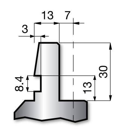
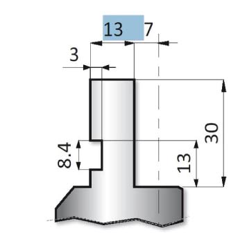
This style of tooling features a 13mm wide tang, with a rectangular section groove on the side of the punch facing the operator. The tang engages with the receiver within the press brake.
Wila Trumpf Style Tooling:
Wila Trumpf Style tooling features a 20mm wide tang, with a groove in the front and back of the tang. In addition, the punch is retained into the holder with one of two mechanisms as follows.
Press Brake Tooling Charts
Benefits of Press Brake Tooling Chart
The importance of the press brake tooling chart in sheet metal fabrication cannot be overstated. Here are some key reasons why it is crucial:
Tool Selection: The chart serves as a guide for selecting the appropriate tooling setups based on the specific requirements of the bending operation. Different materials, thicknesses, and bending angles may necessitate different tooling configurations, and the chart helps operators make informed decisions.
Efficiency: By having a clear reference of available tooling options and their capabilities, operators can streamline the setup process and minimize downtime. They can quickly identify the most suitable tooling arrangement for a particular job, thus increasing overall efficiency in the fabrication process.
Accuracy: Utilizing the correct tooling setup is essential for achieving accurate and consistent bends in sheet metal components. The tooling chart ensures that operators choose the right tools to maintain precision and quality throughout the bending process, reducing the likelihood of errors and rework.
Safety: Using improper tooling setups can pose safety hazards in the workplace, leading to accidents or damage to equipment. The tooling chart helps operators adhere to safety guidelines by ensuring that they select tooling configurations that are appropriate for the intended application, thereby promoting a safer working environment.
Press Brake Shape Chart
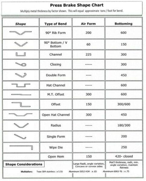
Press brake shape chart is a visual reference guide that illustrates the various bending shapes and configurations that can be achieved using a press brake machine with different tooling setups. This chart typically displays diagrams or drawings of common bending profiles, including:
- V-Bend: Shows a V-shaped bend, formed by using a V-shaped punch and die set.
- U-Bend: Illustrates a U-shaped bend, formed by using a U-shaped punch and die set.
- Offset Bend: Displays a bend where one part of the workpiece is bent at a different angle or position compared to the rest of the piece.
- Hemming: Demonstrates a bend where the edge of the workpiece is folded over onto itself, creating a smooth, rounded edge.
- Box Bend: Shows a bend that forms a box-like shape in the workpiece, typically used for fabricating enclosures or boxes.
- Channel Bend: Illustrates a bend that forms a channel or trough shape in the workpiece, commonly used in structural applications.
- Flange Bend: Displays a bend where one edge of the workpiece is bent to form a flange, allowing for attachment or joining with other components.
- Joggle Bend: Demonstrates a bend where one part of the workpiece is offset or jogged out from the rest of the piece, often used for creating clearance or mating surfaces.
- Hemmed Flange: Combines a flange bend with a hemming operation, resulting in a bent edge with a folded-over hem.
- Rib Bend: Illustrates a bend that forms a rib or raised feature in the workpiece, providing stiffness or reinforcement.
Conclusion
Choosing the right press brake tooling is crucial for achieving accurate, high-quality, and efficient bending operations in sheet metal fabrication. It impacts various aspects of the production process, including accuracy, quality, efficiency, versatility, safety, equipment longevity, and cost-effectiveness. Therefore, careful consideration and proper selection of tooling sets are essential for ensuring successful and profitable fabrication operations.
Reviewed by 1 user
Press brake tools
Very good press brake manufacturer, selling your press brake machine is very safe.