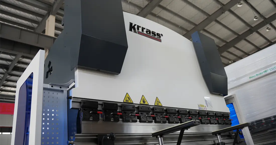
NC press brakes can bend metal more accurately, reducing the amount of waste generated during the sheet metal forming process. In the previous article, we told you about the installation of NC press brake with E21. In this article, we will tell you how to operate and use NC press brake with E21:
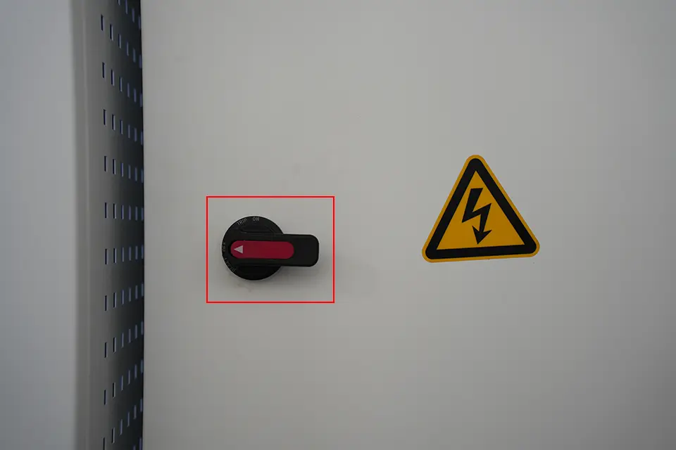
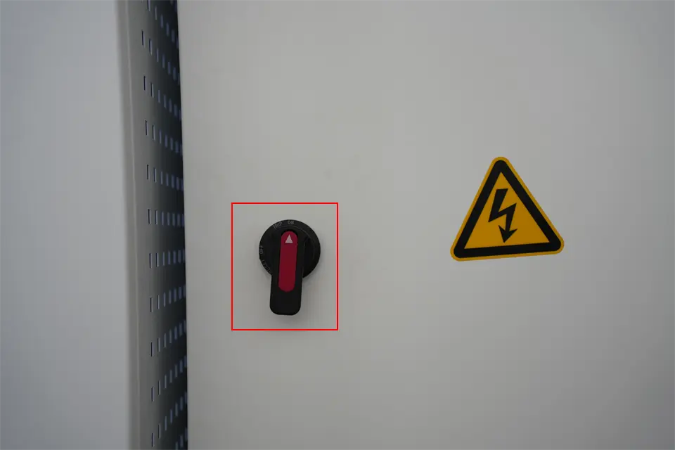
1. First turn on the main power knob on the electric cabinet;
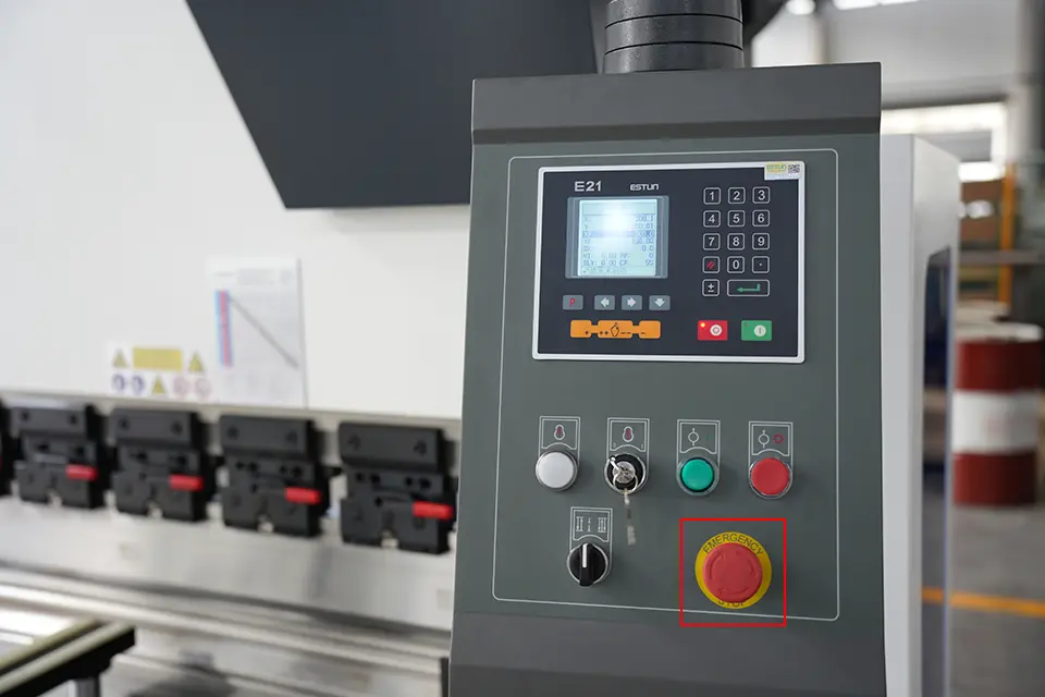
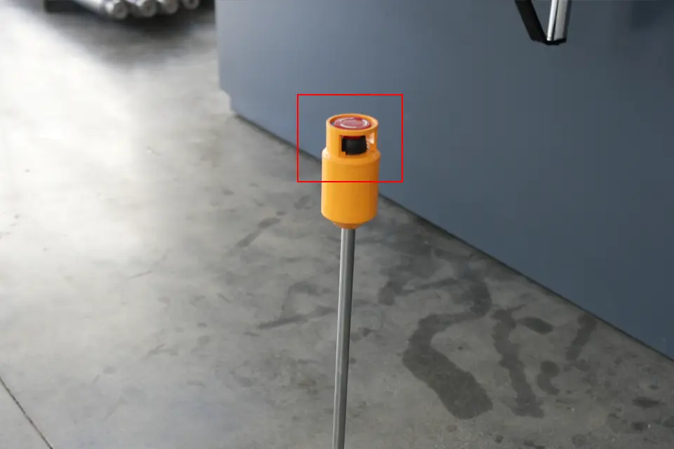
2. Check the emergency stop button on the controller panel of the NC press brake and the foot switch, and turn them clockwise to restore them;
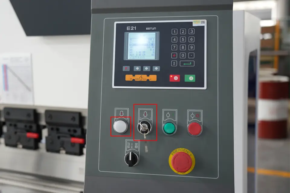
3. Turn the main power key on the controller panel clockwise to turn on the main power of the controller;
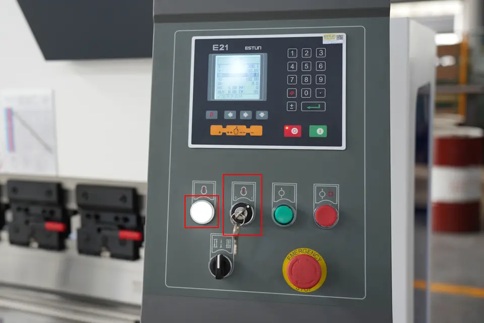
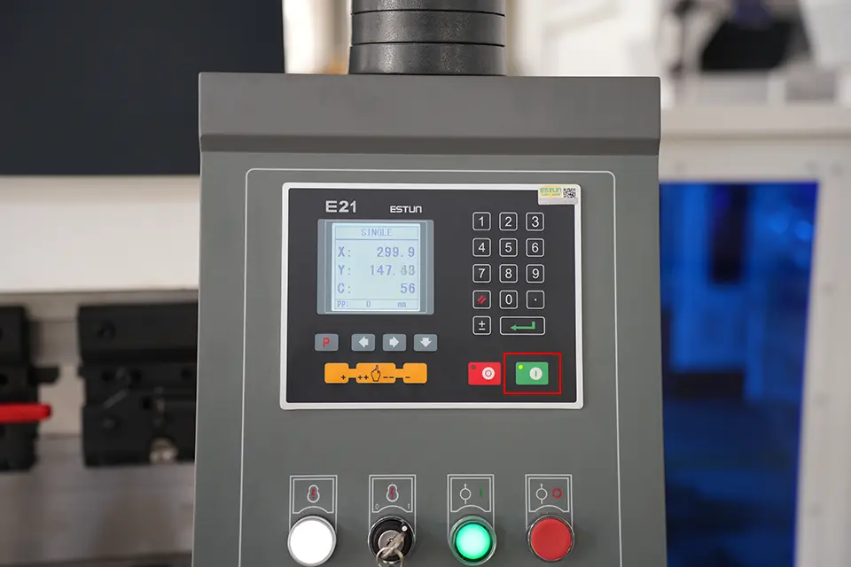
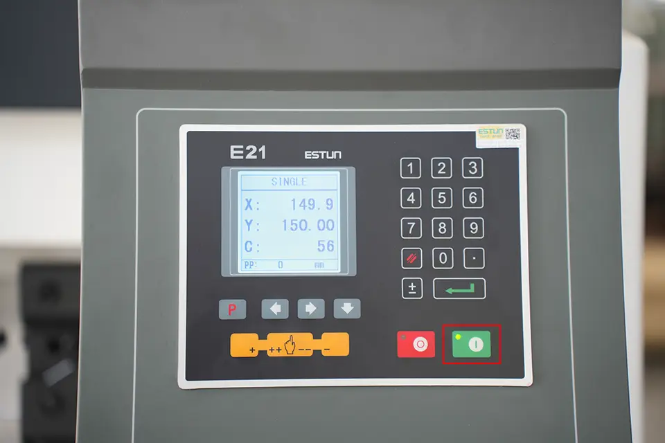
4. Click the green start button on the controller panel, the green indicator light is on, and the device starts, as shown in the figure:
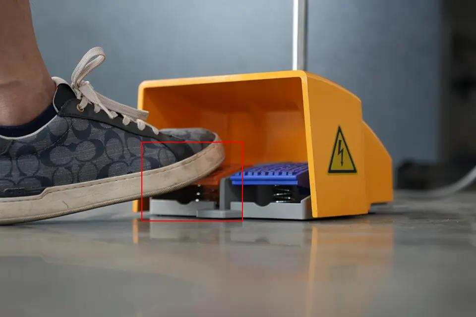
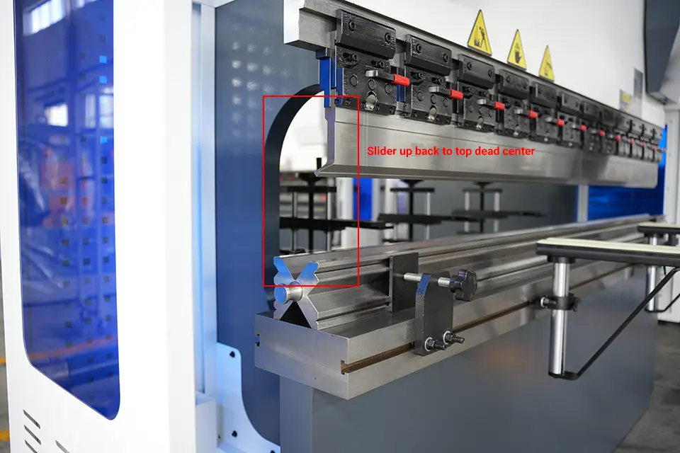
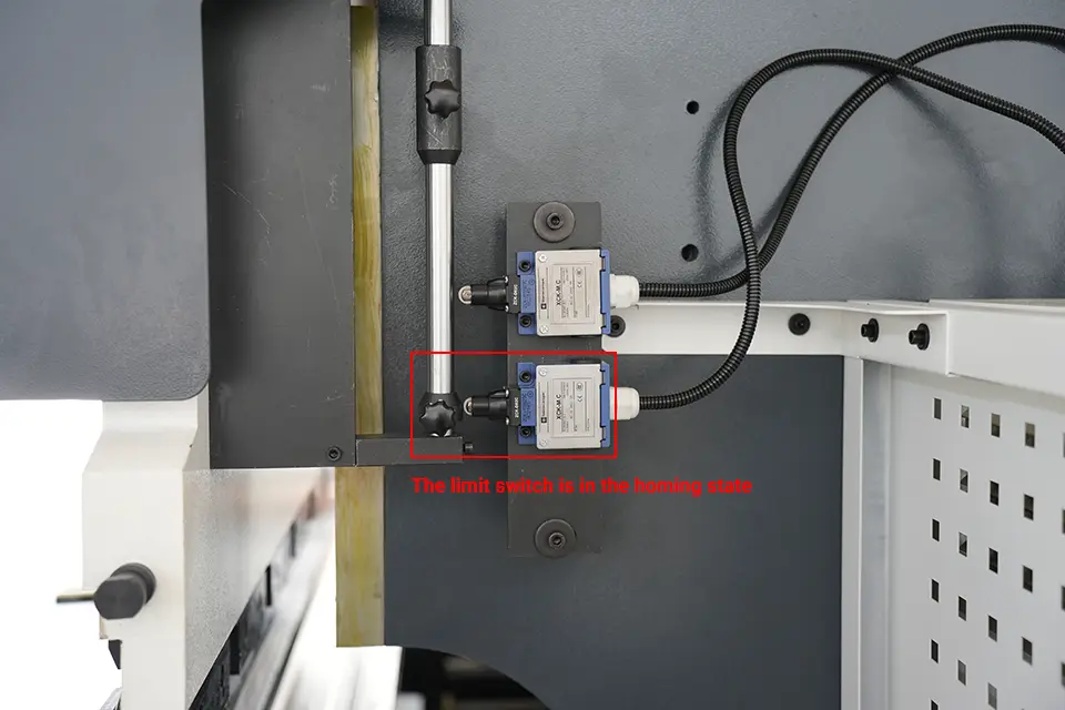
5. Use your foot to step on the return switch on the left side of the foot switch to make the slider of the bending machine return upward to the top dead center. At this time, the limit switch should be in the homing state;
How to adjust the X axis?
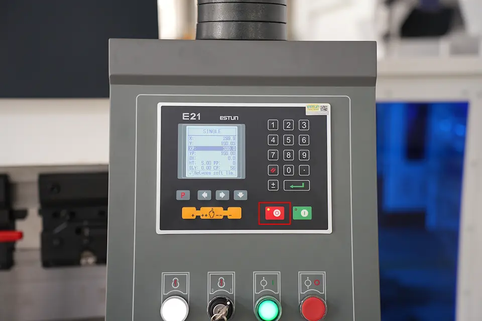
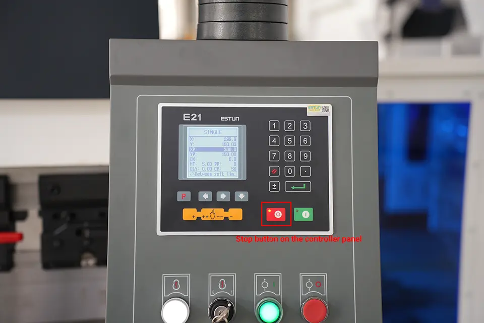
6. Click the red stop button on the controller panel, the red indicator light is on, and the device stops, as shown in the figure:
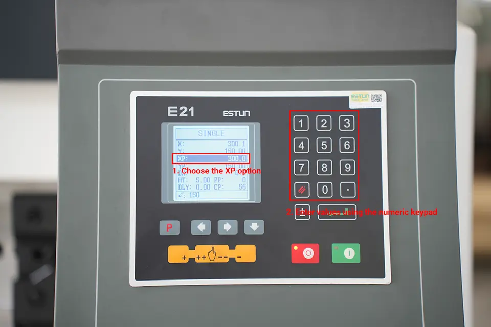
7. First select the XP option, use the numeric keypad on the right to input the value to be set, and then press the Enter key to confirm;
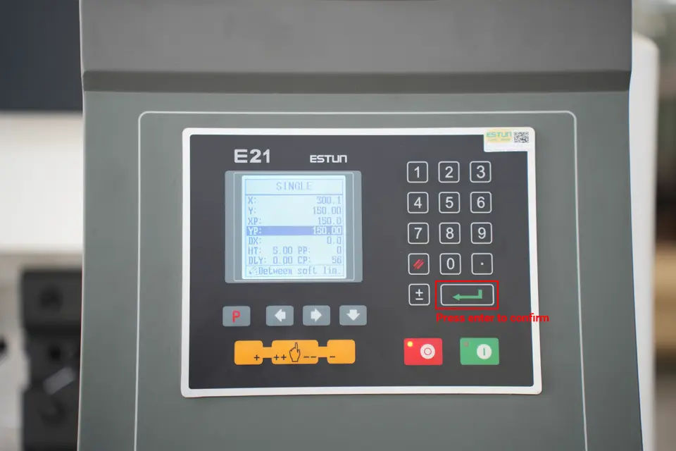
8. After the input is complete, press the Enter key to confirm, as shown in the figure;
9. Click the green start button on the control panel again, the green indicator light is on, the device starts, and the X-axis starts to move according to the set parameters, as shown in the figure:
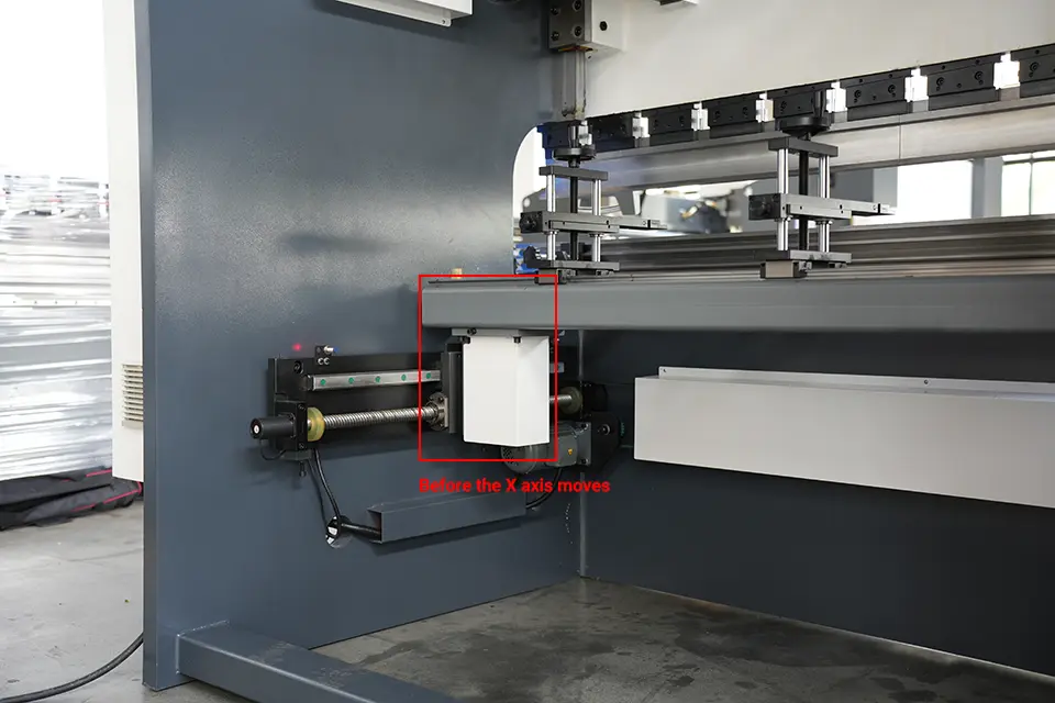
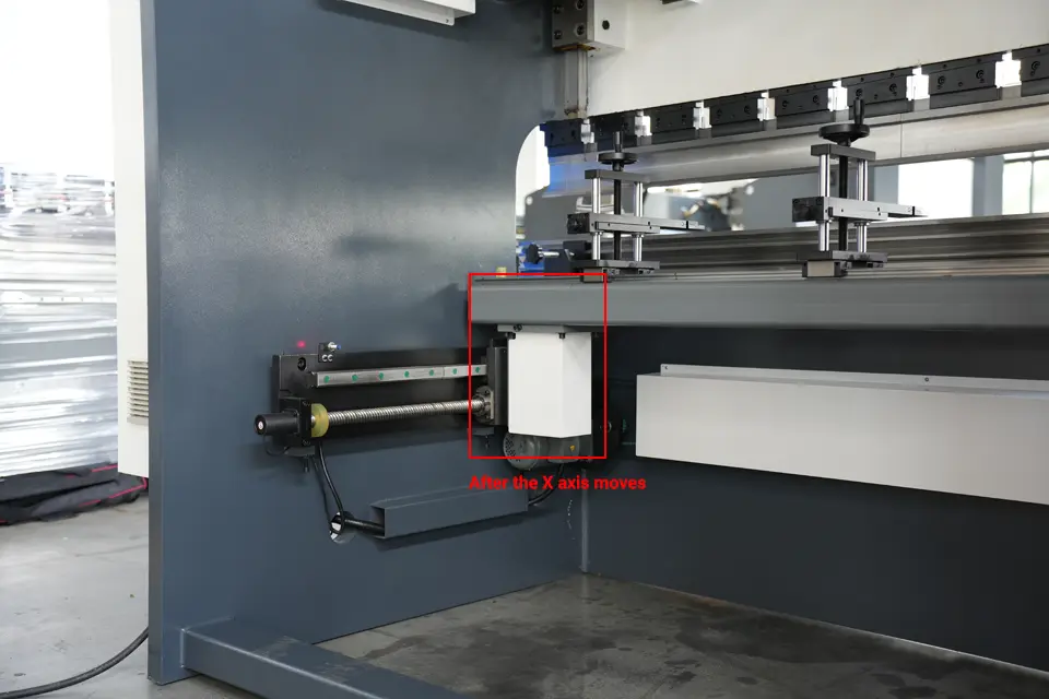
How to adjust the Y axis?
10. Click the red stop button on the controller panel, the red indicator light is on, and the device stops, as shown in the figure:
11. Click the down button, select the YP option, and use the numeric keypad on the right to enter the value to be set;
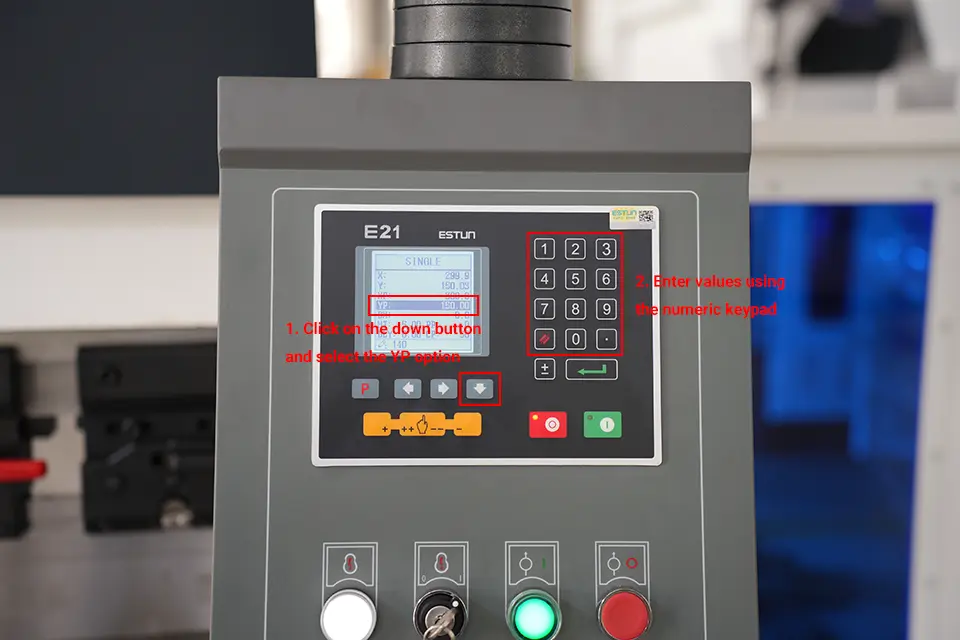
12. After the input is complete, press the Enter key to confirm, as shown in the figure;
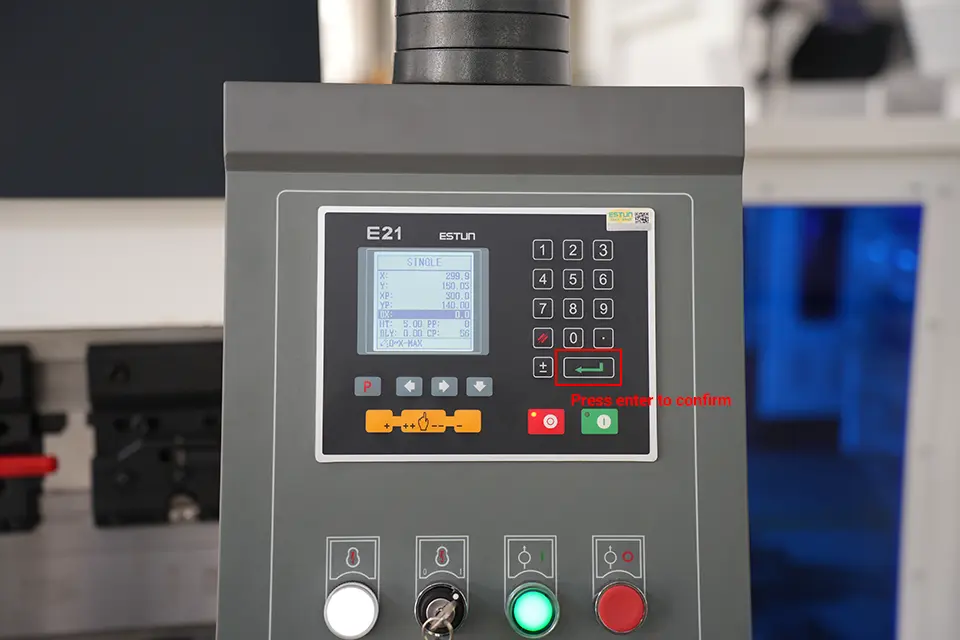
13. Click the green start button on the control panel again, the green indicator light is on, the device starts, and the Y-axis starts to move according to the set parameters until the movement is completed. as the picture shows:
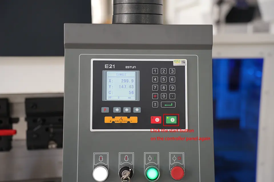
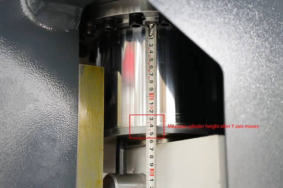
Notice:
1. When the slider returns to the top dead center upwards, or when it reaches the conversion point downwards, the limit switch on the side must be in the homing state;

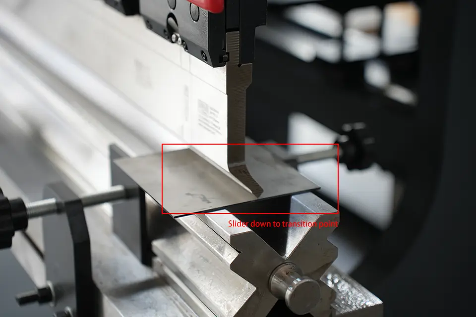
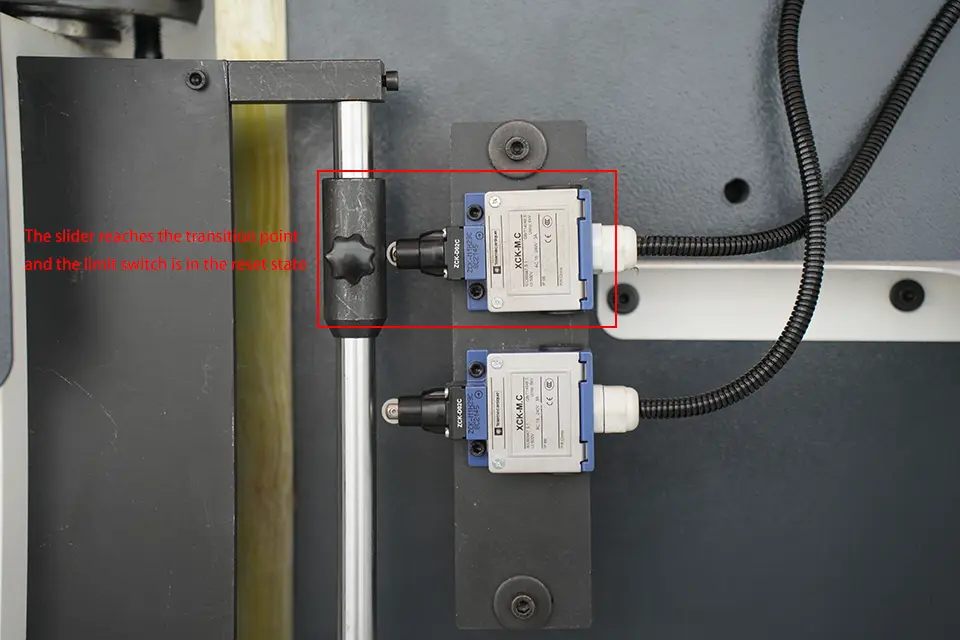
2. After pressing the green start button on the controller, you need to ensure that the values on the controller meet: X=XP, Y=YP (within the allowable error range);
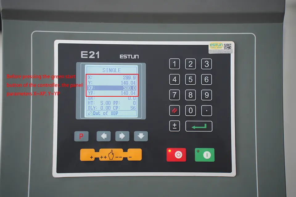
Only when the above two conditions are met, the NC press brake can work normally.
The above is the detailed process of how to operate NC press brake with E21, I hope it can help you. If you just received the machine and don't know how to turn it on, you can refer to our article:
