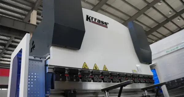
Metal press brakes are essential tools in the metalworking industry, utilized to alter the shape, size, or properties of metal materials through the application of pressure. They are extensively employed across various sectors such as automotive, aerospace, construction, electronics, and electrical appliances. With technological advancements, metal presses have evolved to cater to diverse processing requirements. This article aims to provide an overview of several common types of metal presses, including mechanical, hydraulic metal brake press, pneumatic, CNC brakes, and composite presses, by discussing their definitions, characteristics, and application scenarios.
Today we will focus on the hydraulic metal brake press, which is also one of the most common and widely used bending equipment.
Hydraulic Metal Brake Press
What is It?
A hydraulic metal press is a type of equipment that uses liquid as the working medium, leveraging the incompressibility of the liquid and the principles of hydraulic transmission to achieve energy conversion and mechanical operation. The hydraulic pump efficiently converts the pressure energy of the hydraulic fluid into mechanical energy, enabling various processing treatments on metal materials, such as molding, pressing, bending, and tensile operations.
Features
(1) Hydraulic metal presses offer high pressure and an adjustable stroke, making them suitable for processing large or heavy workpieces. The ability to adjust the stroke length allows for versatility in different processing requirements, ideal for high-strength applications where significant force is necessary. These presses provide higher precision, enabling the processing of complex shapes with exceptional accuracy. They maintain consistent quality across multiple production runs, which is crucial for precision tasks in industries like aerospace and automotive.
(2) Another notable feature is their low noise and vibration levels. Hydraulic metal presses operate quietly, contributing to a more comfortable and less disruptive working environment. The minimized vibrations reduce wear and tear on the machine, extending its lifespan, and enhance safety and ergonomics for operators, promoting better workplace conditions.
(3) Hydraulic metal presses are also known for their energy efficiency. They optimize energy use, reducing operational costs, and their efficient hydraulic systems ensure maximum output with minimal energy consumption. This makes them environmentally friendly and supportive of sustainable manufacturing practices.
(4) Furthermore, these presses are highly versatile, capable of performing a wide range of operations such as molding, pressing, bending, and tensile tasks. They can handle various metal materials and thicknesses, making them suitable for diverse industries, from construction to electronics.
(5) Lastly, hydraulic metal presses often incorporate advanced control systems, such as CNC, for precise and automated operations. These modern control systems allow for easy programming and monitoring of tasks, improving efficiency and reducing human error. They also facilitate integration with other manufacturing systems, streamlining production processes.
Application
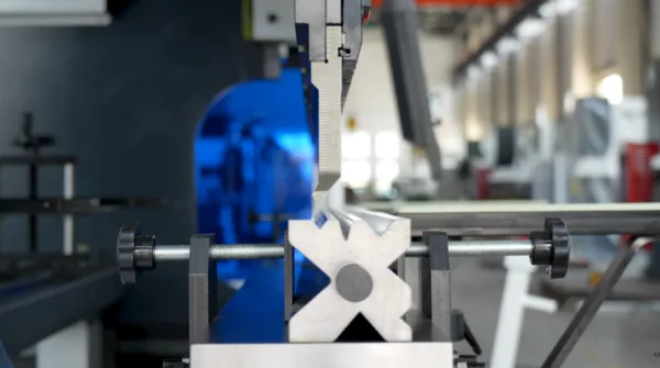
This equipment is widely used in the forging industry because of its high efficiency, precision and stable processing capability. It can not only be used for die forging, but also for free forging, and it is also handy for calibrating and equalizing processing of plates.
Especially in those production occasions that have high requirements for pressure tonnage and strict standards for processing accuracy, hydraulic metal presses have shown their excellent performance and irreplaceable role. Whether in the field of aviation, aerospace, automobile, ship or other metal structure manufacturing, it is one of the important equipment to ensure product quality and efficiency.
How Does Hydraulic System Work
1. Start
All electromagnets must not be energized, and the output oil of the main pump is unloaded through the neutral position of valves 6, 21.
2. The main cylinder goes down quickly
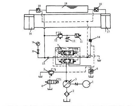
The electromagnets 1Y and 5Y are energized, the valve 6 is in the right position, and the hydraulic control check valve 9 is opened by the control oil through the valve 8. Oil inlet: pump 1-right position of valve 6-valve 13-upper cavity of master cylinder. Oil return circuit: lower cavity of master cylinder-valve 9-right position of valve 6-middle position of valve 21-oil tank.
The slider of the master cylinder descends rapidly under its own weight. Although the pump 1 is at the maximum flow state, it still cannot meet its needs. Therefore, the upper cavity of the master cylinder forms a negative pressure, and the oil from the upper oil tank 15 enters the upper cavity of the master cylinder through the filling valve 14 .
3. The main cylinder approaches the workpiece slowly and pressurizes
When the slider of the master cylinder drops to a certain position and touches the stroke switch 2S, 5Y is de-energized, valve 9 is closed, and the oil in the lower cavity of the master cylinder returns to the tank through the back pressure valve 10, the right position of the valve 6, and the middle position of the valve 21. At this time, the pressure in the upper chamber of the master cylinder rises, the valve 14 is closed, and the master cylinder slowly approaches the workpiece under the action of the pressure oil supplied by the pump 1. After contacting the workpiece, the resistance increases sharply, the pressure further increases, and the output flow of the pump 1 automatically decreases.
4. Keep pressure
When the pressure in the upper chamber of the master cylinder reaches a predetermined value, the pressure relay 7 sends a signal to make 1Y de-energized, the valve 6 returns to the neutral position, and the upper and lower chambers of the master cylinder are closed. The conical surfaces of the check valve 13 and the filling valve 14 ensure a good seal It keeps the main cylinder pressure. The holding time is adjusted by the time relay. During the pressure holding period, the pump is unloaded at the center of the valves 6 and 21.
5. Pressure relief
The return stroke of the master cylinder is over, the time relay sends out a signal, 2Y is energized, and valve 6 is in the left position. Due to the high pressure in the upper chamber of the master cylinder, the hydraulic slide valve 12 is in the upper position, the pressure oil causes the external control sequence valve 11 to open, and the output oil of the pump 1 returns to the oil tank through the valve 11. The pump 1 works at low pressure. This pressure is not enough to open the main spool of the filling valve 14. Instead, the unloading spool of the valve is opened first, so that the oil in the upper cavity of the master cylinder is discharged back to the upper oil tank through this unloading spool opening. The pressure gradually decreases.
When the pressure in the upper chamber of the master cylinder reaches a certain value, valve 12 returns to the lower position, valve 11 is closed, pump 1 pressure rises, valve 14 is fully opened, and the oil inlet path: pump 1-valve 6 left position-valve 9-main Lower cavity of the cylinder. Oil return circuit: upper cavity of master cylinder-valve 14-upper oil tank 15. Realize the rapid return stroke of the master cylinder.
6. The master cylinder stops in situ
When the slider of the master cylinder rises to touch the stroke switch 1S, 2Y loses power, the valve 6 is in the neutral position, the hydraulic control check valve 9 closes the lower cavity of the master cylinder, and the master cylinder stops in its original position. The output oil of pump 1 is unloaded at the neutral position of valves 6 and 21.
7. The lower cylinder is ejected and returned
3Y is energized and valve 21 is in the left position. Oil inlet: pump 1-middle position of valve 6-left position of valve 21-lower cavity of lower cylinder. Oil return path: upper cavity of lower cylinder-left position of valve 21-oil tank. The lower cylinder piston rises and ejects.
3Y is de-energized, 4Y is energized, valve 21 is in the right position, and the lower cylinder piston descends and retracts.
8. Floating blank holder
After the hydraulic press brake piston of the lower cylinder rises to a certain position, the valve 21 is in the neutral position. When the slider of the master cylinder is pressed down, the piston of the lower cylinder is forced to descend along with it. The oil in the lower cavity of the lower cylinder is returned to the oil tank through the throttle 19 and the back pressure valve 20. To maintain the required blank holder pressure in the lower chamber of the lower cylinder, the floating blank holder pressure can be changed by adjusting the valve 20. The upper cavity of the lower cylinder is filled with oil from the oil tank through the center of the valve 21. The relief valve 18 is a safety valve in the lower chamber of the lower cylinder.
Hydraulic Metal Bending & Forming Process
Hydraulic sheet metal bending and forming is a key technology in the metalworking process, which mainly involves the bending and deformation of sheet metal to meet the design requirements of various industrial components and structures.
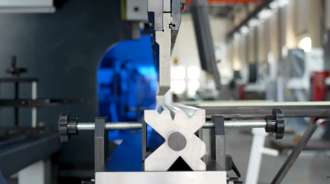
This process can generally be divided into two primary categories: free bending and bottoming. Free bending involves precisely controlling the movement of the upper die on the bending machine to bend the sheet metal along a pre-designed line, achieving the angle and radius specified in the drawing. This method necessitates accurate positioning and adjustment of the die to ensure the precision and repeatability of the bend.
Bottoming, on the other hand, is a more traditional and straightforward method. In this process, the upper die of the bending machine is pressed down to its lowest position, where the combined pressure between the upper and lower dies acts on the sheet metal to create the desired bend. This method is typically used for thicker and heavier plates, as it provides more uniform stress distribution and greater bending stability. Both free bending and bottoming aim to achieve the accurate forming of sheet metal parts, ensuring they meet the requirements of the engineering design while maintaining efficiency and cost-effectiveness.
Typical Defects and Their Causes
Bending Springback
During the bending and forming process, the neutral layer of the sheet metal will be affected by elastic deformation, causing the size and shape of the finished product to deviate from the design requirements. The main reasons for this include the elastic properties of the neutral layer and improper processing of the material.
How to Solve
(1) When bending deformation, the elastic deformation of the plate will increase the amount of rebound due to the elastic deformation of the plate. Therefore, the plate should be annealed before bending, especially for materials that have been cold work hardened, to improve the internal stress organization of the plate, to reduce the rebound problem during processing effectively.
(2) After the sheet metal bending process is formed, the bending parts will recover due to the elastic deformation of the plate, resulting in a slightly larger bending inner diameter and angle than the theoretical value. In order to minimize the effect of this rebound, you can appropriately increase the size of the deformation in the bending process, so that the final product meets the design requirements.
(3) Using a small inner diameter of the upper mold for multiple point bending, through multiple bending deformation can effectively reduce or eliminate the rebound phenomenon, and improve the accuracy and stability of bending and forming.
Bending Cracks
During the bending and forming process, the neutral layer of the sheet metal undergoes elastic deformation, which can cause the size and shape of the finished product to deviate from the design specifications. The primary causes of bending cracks include the elastic properties of the neutral layer and improper material processing.
How to Solve
(1) Adjust the die clearance as well as the uniformity, so that the quality of the section of punching and shearing can be improved to ensure that the section is smooth and straight, and to avoid the appearance of defects such as burrs and cracks.
(2) Take the direction of raw material rolling as the basis, and utilize the nesting software to carry out reasonable scheduling. If the bending direction is the same as the raw material grain direction, the minimum value of the bending radius should be increased appropriately; if the bending direction is perpendicular to the direction of the raw material grain, the minimum value of the bending radius should be reduced appropriately. Ensure that the angle between the direction of the raw material grain and the bending line should generally be about 60 °, the minimum above 30 °.
(3) At the position where multiple bending edges intersect, stop-crack holes should be arranged according to the permissible conditions. The size of the stop-crack hole should be greater than or equal to the thickness of the raw material plus the inside diameter of the bend, when the bending line appears at right angles, increase the width of the stop-crack groove should be greater than two times the thickness of the raw material plus the inside diameter of the bend.
(4) Bending process equipment in accordance with the requirements of the time node lubrication and maintenance, reduce flow resistance, to ensure stable operation of the equipment and long-term use of continuity.
Hydraulic Press Brake vs. Mechanical Press Brake: Which is Right for You
Throughout the long history of the sheet metal working industry, engineers have designed and adapted many types of press brakes to bend sheet metal. Different types of press brakes employ various methods to achieve this universal purpose.
Historically, the mechanical press brake was the primary bending machine. Operated by a crank mechanism, the mechanical press brake is limited by its mechanical transmission and control system, which cannot meet the modern requirements for precision and flexibility in sheet metal processing.
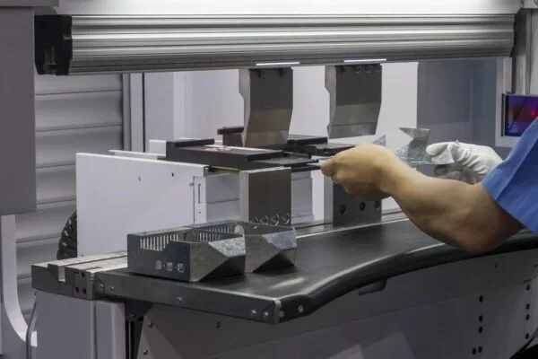
The hydraulic press brake, whose origins date back about 100 years, represents a significant evolution. The primary difference between a mechanical press brake and a hydraulic press brake lies in their transmission components. A hydraulic press brake uses a hydraulic pump to operate. The pressure generated by the hydraulic pump drives synchronized hydraulic cylinders, which then apply force to the material, bending it to the desired angle.
The use of hydraulics allows for smoother operation and greater control. This results in more accurate overall bending lengths, even for larger, more complex parts. Hydraulic brakes are safer and easier to control than mechanical brakes and typically allow for multiple speed settings. They also enable more precise bending, providing greater control during the bending process.
Over the past few decades, hydraulic press brakes have been continuously improved and have gradually replaced mechanical devices, becoming the mainstream choice in the industry.
Hydraulic Metal Brake Press Maintenance Care
Press Brake Maintenance: Preparing the Press Brake
Before beginning any cleaning or maintenance on a press brake, it is essential to prepare the machine properly to ensure the safety of both yourself and your colleagues. Follow these recommended steps:
Initial Inspection: At the start of the work shift, inspect the machine to ensure the table and die area are free of residues from the previous shift.
Area Delimitation: Delimit the maintenance area with barriers and signs to warn others.
Tool Positioning: Lower the mobile beam until the tip of the top tool touches the bottom tool, keeping the tools closed until all maintenance work is complete.
Power Down: Switch off the power supply and padlock the main disconnector switch on the electrical cabinet door.
Mains Switch: Turn the mains switch to the 0 position.
Five Precautions to Take During Press Brake Maintenance
Ensuring the longevity and efficiency of your press brake involves not only regular maintenance but also adhering to essential safety precautions. Proper maintenance, combined with correct usage, significantly enhances the machine's performance. Always follow the specific instructions provided in your press brake maintenance manual. Below are five crucial precautions to observe:
Avoid Solvents and Flammable Materials:
It is critical to avoid using solvents and flammable materials during the maintenance of a press brake. Solvents can damage seals and other components, while flammable materials pose a significant fire risk. Instead, use manufacturer-recommended cleaning agents and lubricants that are safe for use with your specific press brake model.
Environmental Care:
During maintenance, take care to prevent the dispersion of cooling lubricants and other contaminants into the environment. Use containment systems and spill kits to manage any potential leaks or spills. Proper disposal methods should be followed for all waste materials to ensure compliance with environmental regulations and to protect the workplace and surrounding areas.
Suitable Equipment:
When accessing the higher parts of the press brake, use suitable equipment such as ladders, scaffolding, or hydraulic lifts. Ensure that this equipment is stable and designed for the task at hand. Using the right tools not only enhances safety but also allows for more thorough and efficient maintenance.
No Climbing:
Never climb on parts of the press brake, as they are not designed to support the weight of a person. Climbing on the machine can lead to accidents and cause damage to the equipment. Always use designated access points and equipment to reach elevated areas safely.
Safety Devices:
After completing maintenance tasks, it is crucial to reinstall and secure all safety devices and guards that were removed, opened, or disabled. Safety devices, such as interlocks, light curtains, and barriers, are designed to protect operators from hazards associated with press brake operation. Ensuring these are in place and functioning correctly helps prevent accidents and ensures the machine operates safely.
By adhering to these precautions, you not only maintain the efficiency and longevity of your press brake but also ensure a safe working environment for all operators and maintenance personnel.
Conclusion - Why Use Hydraulic Press Brakes?
Press brakes are essential for accurately bending sheet and plate metals to precise angles and lengths. Their versatility and precision make them indispensable in various metalworking applications.
These machines play a vital role in producing specialized parts across numerous industries, including automotive, aviation, agriculture, energy, transportation, and military sectors. The type of press brake needed for effective forming depends on specific production requirements and the materials used. However, a reputable metal service center can help determine the most suitable equipment for the job, providing solutions tailored to diverse bending needs.
For any metal operation or fabricator, the presence of a robust hydraulic metal brake press is crucial for success.
